
1. Introducción
The COTEC SP-4000-148 is a high-frequency pure sine wave inverter designed to convert 48VDC battery power into 120VAC household electricity. This inverter delivers a continuous output of 4000W, making it suitable for various applications requiring stable and clean AC power. Its robust design and advanced features ensure reliable performance and protection for your connected devices.
Características principales:
- Salida de onda sinusoidal pura para electrónica sensible.
- Capacidad de control remoto de encendido/apagado (terminal verde).
- Entrada y salida totalmente aisladas para mayor seguridad.
- Temperature & load controlled cooling fan.
- Interfaz fácil de usar con indicadores de estado LED de 3 colores.
- Frecuencia de salida (50/60 Hz) seleccionable mediante interruptor DIP.
- Vol de salidatagy seleccionable mediante interruptor DIP.
- Modo de ahorro de energía ajustable mediante resistencia variable.
- Comprehensive input protections: Reverse Polarity (Fuse), Under Voltage, sobre voltage.
- Extensive output protections: Short Circuit, Overload, Over Temperature.
- Caja de aluminio para interiores tipo 1.
- Aprobado por E13 / UL / CE / FCC.
2. Información de seguridad
Read all instructions and warnings carefully before installing or operating the inverter. Failure to follow these instructions may result in electric shock, fire, serious injury, or death.
Precauciones generales de seguridad:
- Peligro eléctrico: Este inversor produce alto volumentage AC power. Treat the output terminals with the same respect as any utility AC outlet.
- Personal calificado: La instalación y el mantenimiento sólo deben ser realizados por personal calificado.
- Ventilación: Ensure adequate ventilation around the inverter. Do not block ventilation openings. Overheating can cause damage or fire.
- Ambiente: Do not expose the inverter to rain, snow, spray, or any liquids. Do not operate in areas with flammable fumes or gases.
- Toma de tierra: El inversor debe estar correctamente conectado a tierra. Consulte la sección de instalación para obtener instrucciones sobre la conexión a tierra.
- Seguridad de la batería: Work near lead-acid batteries is dangerous. Batteries can generate explosive gases. Ensure proper ventilation and wear eye protection.
- Entrada de CC: Connect the DC input cables with correct polarity. Reverse polarity will blow the internal fuse and void the warranty.
- Sobrecarga: No exceda la potencia de salida nominal del inversor. La sobrecarga puede dañar el inversor y los aparatos conectados.
- Mantenimiento: Before performing any maintenance or cleaning, disconnect all power sources (DC and AC).
3. Producto terminadoview
The COTEC SP-4000-148 inverter features a robust aluminum enclosure and clearly labeled connection points for ease of installation and operation. Familiarize yourself with the components before proceeding with installation.

Figura 3.1: En general view of the COTEC SP-4000-148 Pure Sine Wave Inverter. This image shows the blue aluminum casing and the grey end caps with ventilation slots.
Front Panel (AC Output Side):
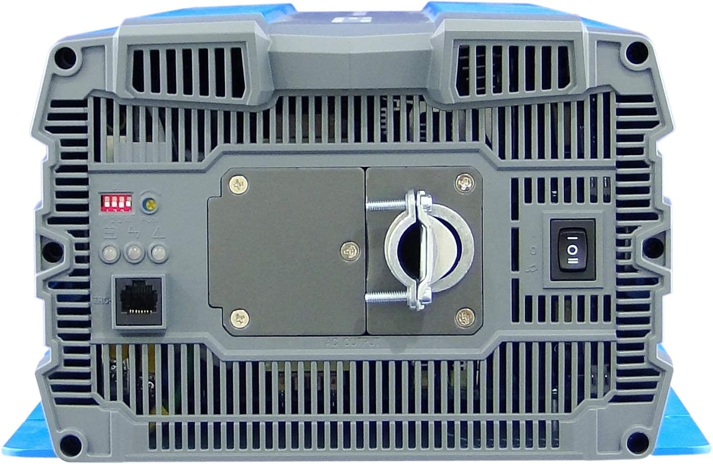
Figure 3.2: Front panel of the inverter. This view highlights the AC output terminal, the remote control terminal (green), LED status indicators, DIP switches, and the main power switch.
- Terminal de salida de CA: Hardwire connection for 120VAC output.
- Remote Control Terminal (Green): For connecting an optional remote ON/OFF switch.
- Indicadores de estado LED: Provide visual feedback on inverter status (Power, Fault, Overload).
- Interruptores DIP: Used to select output frequency (50/60 Hz) and output voltage.
- Power Saving Mode Resistor: Adjustable resistor for fine-tuning power saving mode.
- Interruptor principal: Controla la potencia del inversor.
Rear Panel (DC Input Side):

Figure 3.3: Rear panel of the inverter. This view shows the DC input terminals (red for positive, black for negative) and the chassis ground connection point.
- Terminales de entrada de CC: Heavy-duty terminals for connecting to the 48VDC battery bank. Ensure correct polarity (Red for Positive, Black for Negative).
- Chassis Ground Terminal: Para conectar el inversor a una toma de tierra.
- Rejillas de ventilación del ventilador de refrigeración: Ensure these vents are not obstructed for proper heat dissipation.
4. Instalación
Una instalación correcta es crucial para el funcionamiento seguro y eficiente de su inversor. Siga estos pasos cuidadosamente.
4.1 Montaje del inversor
- Choose a dry, well-ventilated location away from direct sunlight, heat sources, and moisture.
- Mount the inverter on a non-combustible surface.
- Ensure there is at least 6 inches (15 cm) of clear space around all sides of the inverter for proper airflow.
- Use appropriate fasteners to secure the inverter firmly to the mounting surface.
4.2 Conexión de entrada de CC
ADVERTENCIA: Ensure the battery bank is disconnected or isolated before making any connections. Use appropriately sized cables and fuses/breakers.
- Connect the positive (+) DC cable (typically red) from your 48VDC battery bank to the red positive (+) terminal on the inverter's rear panel.
- Connect the negative (-) DC cable (typically black) from your 48VDC battery bank to the black negative (-) terminal on the inverter's rear panel.
- Ensure all DC connections are tight and secure to prevent loose connections and arcing.
- Install an external DC fuse or circuit breaker between the battery bank and the inverter's positive terminal, as close to the battery as possible. Consult the specifications for appropriate fuse sizing.
4.3 Conexión de salida de CA
The SP-4000-148 uses a hardwire AC output connection.
- Ensure the inverter is OFF and all DC power is disconnected.
- Connect your AC load wiring to the designated AC output terminal block on the front panel.
- Follow all local electrical codes for AC wiring.
- Ensure all AC connections are secure.
4.4 Puesta a tierra
The inverter chassis must be properly grounded.
- Connect a ground wire from the chassis ground terminal on the inverter's rear panel to a reliable earth ground point.
- Ensure the ground connection is secure and meets all local electrical codes.
4.5 Conexión del control remoto (opcional)
If using an optional remote control, connect it to the green terminal block on the front panel according to the remote control's instructions.
5. Operación
Once the inverter is properly installed and all connections are secure, you can begin operation.
5.1 Encendido / Apagado
- Ensure all DC and AC connections are correct and secure.
- If an external DC breaker is installed, ensure it is closed (ON).
- Flip the main power switch on the inverter's front panel to the 'ON' position.
- The LED indicators will illuminate, and the cooling fan may briefly activate.
- Para apagar, coloque el interruptor de encendido principal en la posición "APAGADO".
5.2 indicadores de estado LED
The inverter features 3-color LED indicators to display its operational status:
- LED verde: Indica funcionamiento normal.
- LED amarillo: Indicates a warning or abnormal condition (e.g., low battery, minor overload). Refer to troubleshooting.
- LED rojo: Indicates a fault or critical error (e.g., severe overload, over-temperature, short circuit). The inverter will typically shut down. Refer to troubleshooting.
5.3 Configuración del interruptor DIP
The DIP switches on the front panel allow configuration of output frequency and voltage. Refer to the detailed specifications or the label on the inverter for specific switch positions for desired settings.
- Frecuencia de salida: Select between 50 Hz or 60 Hz.
- Vol de salidatage: Select desired AC output voltage (por ejemplo, 100 V, 110 V, 115 V, 120 V).
NOTA: Always power off the inverter before changing DIP switch settings.
5.4 Modo de ahorro de energía
The power saving mode can be adjusted via the variable resistor on the front panel. This mode reduces standby power consumption when no load or a very light load is detected. Adjust the resistor to set the threshold for entering/exiting power saving mode.
6. Mantenimiento
El mantenimiento regular garantiza la longevidad y el rendimiento óptimo de su inversor.
- Limpieza: Limpie periódicamente el exterior del inversor con un paño seco y suave. Asegúrese de que las aberturas de ventilación estén libres de polvo y residuos. No utilice limpiadores líquidos.
- Comprobaciones de conexión: Annually inspect all DC and AC connections for tightness. Loose connections can cause overheating and damage.
- Mantenimiento de la batería: Siga las recomendaciones del fabricante de la batería para el mantenimiento, incluida la verificación de los niveles de electrolito (para baterías inundadas) y la limpieza de los terminales.
- Ambiente: Asegúrese de que el entorno operativo permanezca dentro de los rangos de temperatura y humedad especificados.
7. Solución de problemas
Esta sección proporciona soluciones a problemas comunes que puede encontrar con su inversor.
| Problema | Posible causa | Solución |
|---|---|---|
| Inverter does not turn on (No LEDs) | No DC input power; Blown DC fuse/breaker; Loose DC connections; Reverse polarity. | Compruebe el volumen de la bateríatage; Check external DC fuse/breaker; Verify DC connections are tight and correct polarity. |
| Red LED illuminates, inverter shuts down | Overload; Short circuit on AC output; Over-temperature; Input over/under voltage. | Reduce AC load; Check AC wiring for short circuits; Allow inverter to cool down; Verify battery voltage está dentro del rango operativo. |
| Yellow LED illuminates, intermittent operation | Minor overload; Low battery voltagAdvertencia electrónica; Advertencia de alta temperatura. | Reduce AC load; Recharge batteries; Ensure adequate ventilation. |
| No AC output, Green LED is on | AC output wiring issue; Faulty AC appliance. | Check AC output connections; Test with a different AC appliance. |
| Cooling fan runs constantly or loudly | High ambient temperature; Heavy load; Obstructed vents. | Ensure proper ventilation; Reduce load if possible; Clean vents. |
8. Especificaciones
The following table details the technical specifications for the COTEC SP-4000-148 Pure Sine Wave Inverter.

Figure 8.1: Detailed technical specifications for the COTEC SP-4000 series, including input, output, protection, and environmental parameters.
| Especificación | Valor |
|---|---|
| Marca | COTEK |
| Nombre del modelo | Serie SP |
| Quétage | 4000 vatios |
| Vol de entradatage | 48 voltios CC |
| Potencia de salida | 4000 vatios |
| Frecuencia de salida | 60 Hz (Selectable) |
| Tomas de corriente totales | 1 (Hardwire) |
| Standby Power Shutoff | High Efficiency (Adjustable) |
| Tipo de recinto | Type 1 Indoor Aluminum Enclosure |
| Aprobaciones | E13 / UL / CE / FCC |
| Código Postal | 648152674771 |
| Número de pieza del fabricante | SP-4000-148 |
Dibujos Mecánicos:

Figure 8.2: Mechanical drawings providing dimensions for the COTEC SP-4000 series inverter, useful for installation planning.
9. Garantía y soporte
COTEK products are manufactured to high-quality standards. This product is covered by a manufacturer's warranty against defects in materials and workmanship. Please refer to the warranty card included with your product or visit the official COTEC webSitio para conocer los términos y condiciones detallados de la garantía.
Atención al cliente:
For technical assistance, troubleshooting, or warranty claims, please contact COTEC customer support through their official channels. Have your product model number (SP-4000-148) and purchase information ready when contacting support.
- Websitio: www.cotek.com.tw (Example, por favor verificar oficial websitio)
- Correo electrónico: support@cotek.com (Example)
- Teléfono: +1-XXX-XXX-XXXX (Ej.ample)