1. Introducción
The Yaxun YX-9205 Digital Multimeter is a versatile and reliable instrument designed for measuring various electrical parameters. It is suitable for professional electricians, hobbyists, and students for testing and troubleshooting electronic circuits and devices. This manual provides essential information for safe and effective operation of your multimeter.
2. Información de seguridad
Always observe safety precautions when using any electrical testing equipment. Failure to do so may result in injury or damage to the multimeter or the equipment under test.
- Asegúrese de que el multímetro esté en buenas condiciones de funcionamiento antes de usarlo.
- No aplicar voltage o corriente que excede los límites máximos especificados para cada rango.
- Desconecte siempre los cables de prueba del circuito antes de cambiar funciones o rangos.
- Tenga cuidado al trabajar con vol.tages superior a 30 V CA RMS, 42 V pico o 60 V CC, ya que representan un peligro de descarga eléctrica.
- Reemplace la batería cuando aparezca el indicador de batería baja para garantizar lecturas precisas.
- No opere el multímetro en atmósferas explosivas o en presencia de gases o polvos inflamables.
- Mantenga los dedos detrás de las barreras de la sonda durante las mediciones.
3. Características del producto
The Yaxun YX-9205 Digital Multimeter offers a range of functions and features for comprehensive electrical testing:
- Multi-scale measurements for various electrical parameters.
- Medidas DC Voltage, Vol ACtage, DC Current, AC Current, Resistance, Capacitance, Diode, and Continuity.
- Transistor hFE gain test function.
- Large LCD display with 4 digits, maximum reading 1999.
- Data Hold function to freeze displayed values.
- Auto Power Off function to conserve battery life.
- Audible continuity signal.
- Indicador de batería baja.
- Integrated kickstand for convenient viewEn.
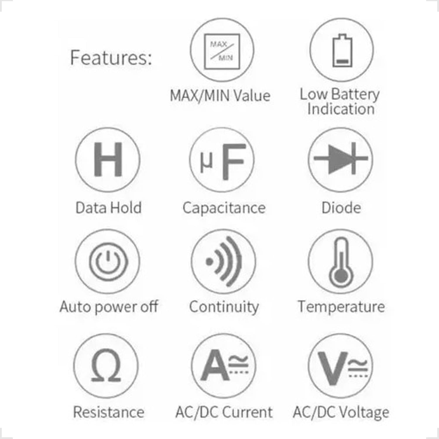
Figure 3.1: Feature Icons. This image displays a set of icons illustrating the key functions and capabilities of the Yaxun YX-9205 Digital Multimeter, such as data hold, capacitance measurement, diode testing, and auto power off.
4. Contenido del paquete
Verifique que todos los artículos estén presentes en su paquete:
- Yaxun YX-9205 Digital Multimeter
- Cables de prueba (rojo y negro)
- 9V Battery (6F22 type)
- Temperature Probe (K-type thermocouple, if included)
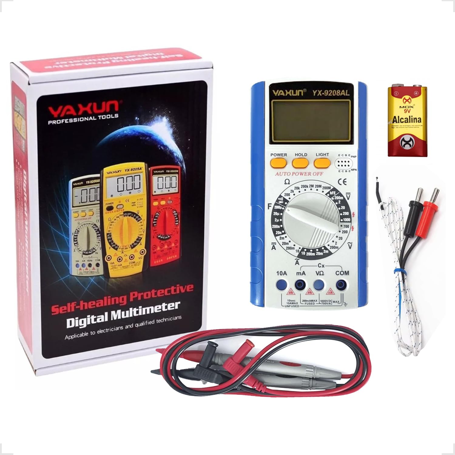
Figure 4.1: Package Contents. This image shows the Yaxun YX-9205 Digital Multimeter, along with its included red and black test leads and a 9V battery.
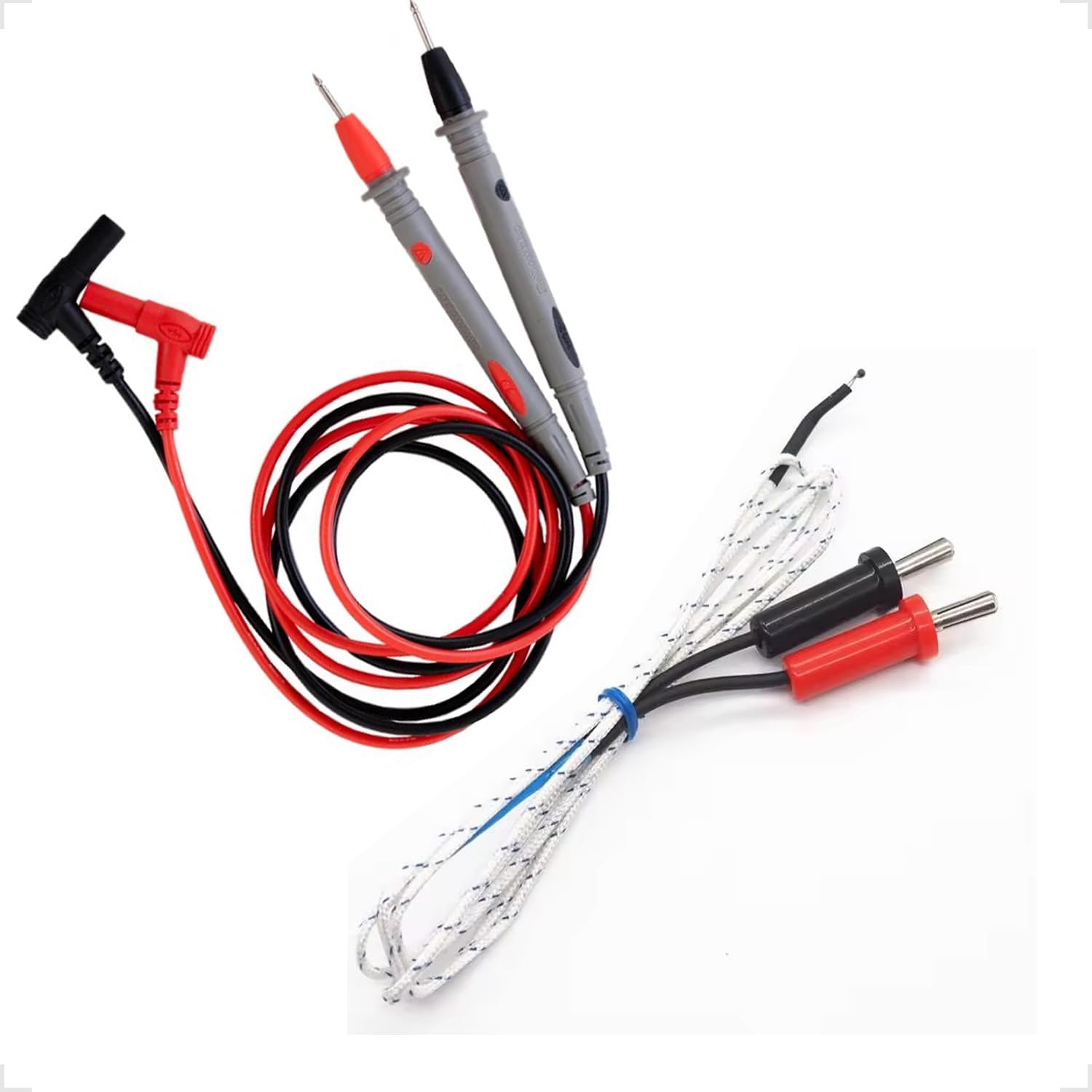
Figure 4.2: Test Leads and Temperature Probe. This image details the included red and black test leads, essential for making electrical measurements, and a white temperature probe.
5. Configuración
5.1 Instalación de la batería
The multimeter requires a 9V battery for operation. Follow these steps to install or replace the battery:
- Asegúrese de que el multímetro esté apagado y los cables de prueba estén desconectados.
- Localice la tapa del compartimiento de la batería en la parte posterior del multímetro.
- Use a screwdriver to remove the screw securing the cover, then lift the cover off.
- Conecte la batería de 9 V al clip de la batería, observando la polaridad correcta.
- Coloque la batería en el compartimiento y vuelva a colocar la tapa, asegurándola con el tornillo.

Figure 5.1: Battery Compartment. This image shows the rear of the multimeter, highlighting the battery compartment cover, which needs to be opened for battery installation or replacement.
5.2 Conexión de cables de prueba
La conexión correcta de los cables de prueba es fundamental para realizar mediciones precisas y seguras:
- Inserte el cable de prueba negro en el conector “COM” (común).
- Para la mayoría de los volúmenestagPara realizar mediciones de corriente, resistencia y continuidad, inserte el cable de prueba rojo en el conector "VΩmA".
- For high current measurements (up to 10A), insert the red test lead into the "10A" jack. Ensure the rotary switch is set to the appropriate current range.
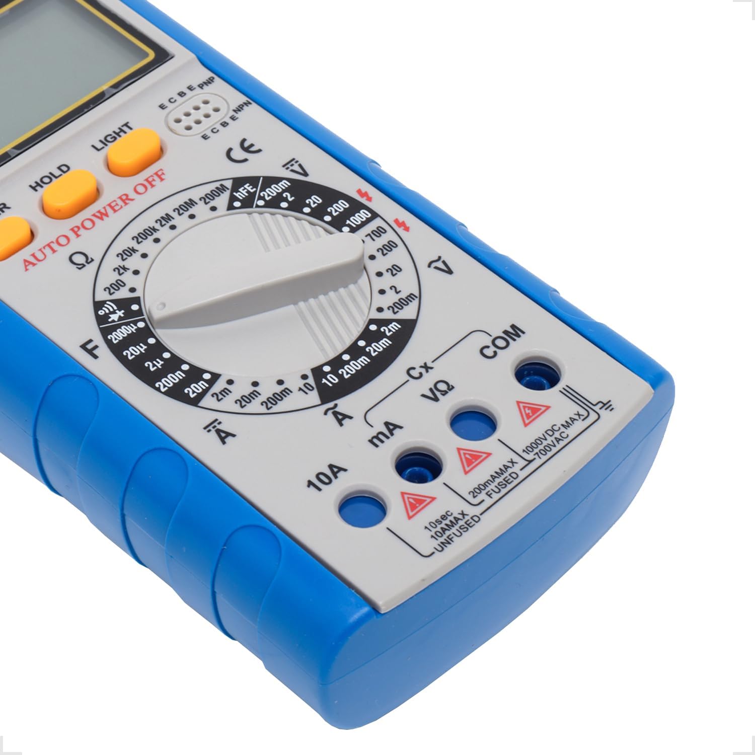
Figure 5.2: Input Jacks. This image provides a detailed view of the multimeter's input jacks: COM (common), VΩmA (for voltage, resistance, and low current), and 10A (for high current measurements).
5.3 Uso del soporte
The multimeter features a built-in kickstand for hands-free operation and improved viewing angle. Simply pull out the kickstand from the back of the unit to deploy it.

Figure 5.3: Multimeter with Kickstand. This image shows the multimeter standing upright with its integrated kickstand extended, providing a stable and convenient viewángulo de inclinación durante el uso.
6. Instrucciones de funcionamiento
6.1 Funcionamiento general
The YX-9205 multimeter is operated primarily using the rotary switch and function buttons.
- Interruptor giratorio: Selects the desired measurement function (e.g., VDC, VAC, ADC, AAC, Ω, F, Diode, Continuity, hFE).
- Botón de encendido: Enciende o apaga el multímetro.
- Botón ESPERA: Congela la lectura actual en la pantalla. Presione de nuevo para liberarla.
- Botón LUZ: Activates the display backlight for better visibility in low-light conditions.

Figura 6.1: Panel de control. Esta imagen proporciona una vista detallada. view of the multimeter's main controls, including the central rotary switch for function selection and the Power, Hold, and Light buttons.
6.2 Medición del volumen de CCtage (VCC)
- Insert the black lead into the COM jack and the red lead into the VΩmA jack.
- Gire el interruptor giratorio al volumen de CC deseado.tagrango e (p. ej., 200 mV, 2 V, 20 V, 200 V, 1000 V). Si el voltage es desconocido, comience con el rango más alto y disminuya según sea necesario.
- Conecte las sondas de prueba al componente o circuito que se va a medir, observando la polaridad.
- Leer el vol.tage valor en la pantalla LCD.
6.3 Medición del volumen de CAtage (VCA)
- Insert the black lead into the COM jack and the red lead into the VΩmA jack.
- Gire el interruptor giratorio al volumen de CA deseado.tagrango e (p. ej., 200 mV, 2 V, 20 V, 200 V, 700 V). Si el voltage es desconocido, comience con el rango más alto.
- Conecte las sondas de prueba al componente o circuito que se va a medir. La polaridad no es crítica para la tensión de CA.tage.
- Leer el vol.tage valor en la pantalla LCD.
6.4 Measuring DC Current (ADC)
Caution: Always connect the multimeter in series with the circuit when measuring current. Never connect it in parallel across a voltage fuente, ya que esto puede dañar el multímetro y el circuito.
- Determine the expected current. For currents up to 200mA, use the VΩmA jack for the red lead. For currents up to 10A, use the 10A jack for the red lead. The black lead always goes into COM.
- Turn the rotary switch to the appropriate DC Current range (e.g., 2mA, 20mA, 200mA, 10A).
- Abra el circuito donde se va a medir la corriente y conecte los cables de prueba en serie.
- Lea el valor actual en la pantalla LCD.
6.5 Measuring AC Current (AAC)
Caution: Always connect the multimeter in series with the circuit when measuring current. Never connect it in parallel across a voltage fuente, ya que esto puede dañar el multímetro y el circuito.
- Determine the expected current. For currents up to 200mA, use the VΩmA jack for the red lead. For currents up to 10A, use the 10A jack for the red lead. The black lead always goes into COM.
- Turn the rotary switch to the appropriate AC Current range (e.g., 2mA, 20mA, 200mA, 10A).
- Abra el circuito donde se va a medir la corriente y conecte los cables de prueba en serie.
- Lea el valor actual en la pantalla LCD.
6.6 Medición de resistencia (Ω)
Caution: Ensure the circuit or component under test is completely de-energized before measuring resistance. Disconnect power and discharge any capacitors.
- Insert the black lead into the COM jack and the red lead into the VΩmA jack.
- Turn the rotary switch to the desired Resistance range (e.g., 200Ω, 2kΩ, 20kΩ, 200kΩ, 2MΩ, 20MΩ, 200MΩ).
- Conecte las sondas de prueba al componente que se va a medir.
- Lea el valor de resistencia en la pantalla LCD.
6.7 Medición de capacitancia (F)
Caution: Ensure capacitors are fully discharged before testing. High voltagLos condensadores electrónicos pueden almacenar cargas peligrosas.
- Insert the black lead into the COM jack and the red lead into the VΩmA jack.
- Turn the rotary switch to the Capacitance (F) function and select the appropriate range (e.g., 20nF, 200nF, 2µF, 20µF, 200µF).
- Conecte las sondas de prueba a través de los terminales del capacitor.
- Lea el valor de la capacitancia en la pantalla LCD.
6.8 Prueba de diodos
- Insert the black lead into the COM jack and the red lead into the VΩmA jack.
- Gire el interruptor giratorio al símbolo de diodo.
- Conecte la sonda roja al ánodo y la sonda negra al cátodo del diodo. La pantalla mostrará el voltaje directo.tagcaída de tensión (normalmente entre 0.5 V y 0.8 V para diodos de silicio).
- Reverse the probes. The display should show 'OL' (Open Loop) for a good diode. A reading in both directions or 'OL' in both directions indicates a faulty diode.
6.9 Prueba de continuidad
- Insert the black lead into the COM jack and the red lead into the VΩmA jack.
- Turn the rotary switch to the Continuity symbol (often shared with the Diode function).
- Conecte las sondas de prueba a través del circuito o componente.
- Si la resistencia es inferior a aproximadamente 50 Ω, sonará un zumbador para indicar continuidad. La pantalla también mostrará el valor de la resistencia.
6.10 Prueba hFE del transistor
- Gire el interruptor giratorio a la posición hFE.
- Identifique si el transistor es NPN o PNP.
- Insert the transistor's emitter, base, and collector leads into the corresponding holes in the hFE socket on the multimeter.
- Lea el valor hFE (ganancia de corriente CC) en la pantalla LCD.
7. Especificaciones
| Parámetro | Rango | Exactitud |
|---|---|---|
| Vol DCtage | 200mV, 2V, 20V, 200V, 1000V | ±(0.5% + 1 dígitos) |
| Vol. CAtage | 200mV, 2V, 20V, 200V, 700V | ±(0.8% + 3 dígitos) |
| Corriente continua | 2 mA, 20 mA, 200 mA, 10 A | ±(0.5% + 1 dígitos) |
| Corriente alterna | 2 mA, 20 mA, 200 mA, 10 A | ±(1.0% + 3 dígitos) |
| Resistencia | 200Ω, 2kΩ, 20kΩ, 200kΩ, 2MΩ, 20MΩ, 200MΩ | ±(0.8% + 1 dígitos) |
| Capacidad | 20nF, 200nF, 2µF, 20µF, 200µF | ±(4.0% + 3 dígitos) |
| Mostrar | 1999 counts, 60 x 31.5mm LCD | |
| Fuente de alimentación | Batería de 9 V (6F22) | |
| Dimensiones (L x An x Al) | 180 x 86 x 35 mm | |
8. Mantenimiento
8.1 Limpieza
Para limpiar el multímetro, limpie la carcasa con un paño.amp Paño y detergente suave. No utilice abrasivos ni disolventes. Asegúrese de que el multímetro esté completamente seco antes de usarlo.
8.2 Reemplazo de batería
When the low battery indicator appears on the display, replace the 9V battery as described in the 'Battery Installation' section (5.1). A weak battery can lead to inaccurate readings.
8.3 Reemplazo de fusibles
Caution: Always disconnect test leads and turn off the multimeter before replacing the fuse. Use only fuses of the specified type and rating.
If the multimeter fails to measure current, the fuse may be blown. To replace the fuse:
- Apague el multímetro y desconecte todos los cables de prueba.
- Open the battery compartment cover as described in section 5.1.
- Retire con cuidado el fusible viejo.
- Install a new fuse of the correct type and rating (e.g., F200mA/250V for mA ranges, F10A/250V for 10A range). Refer to the markings near the fuse holder if available.
- Vuelva a colocar la tapa del compartimiento de la batería y asegúrela con el tornillo.
9. Solución de problemas
| Problema | Posible causa | Solución |
|---|---|---|
| Sin pantalla o pantalla tenue | Batería muerta o débil | Reemplace la batería de 9V. |
| Lecturas incorrectas | Incorrect range selected, poor lead connection, weak battery | Select the correct range, ensure leads are firmly connected, replace battery. |
| No hay medición de corriente | Blown fuse, incorrect lead connection | Check and replace fuse if necessary, ensure leads are in correct current jacks and connected in series. |
| 'OL' (Sobrecarga) mostrado | Measurement exceeds selected range, open circuit | Select a higher range, check for open circuit. |
10. Garantía y soporte
This Yaxun YX-9205 Digital Multimeter is designed for reliability and performance. For specific warranty information, please refer to the purchase documentation or contact your retailer. For technical support or inquiries, please reach out to the Yaxun customer service department or your local distributor.