
1. Producto terminadoview
The Zerone FRM01 is a versatile multifunction relay cycle timer module designed for automation and delay control applications. It offers various timing and latching modes, allowing precise control over connected devices. This module is suitable for a wide range of industrial and hobbyist projects requiring timed switching or repetitive operations.
Características principales:
- Adjustable timing range from 0.1 seconds to 270 hours.
- Multiple operating modes including timing pick/off, timing pull off again, infinite loop timing, latching, and pull/timing.
- High-level pulse input (CH1) for triggering and resetting functions.
- Integrated display for time settings and status.
- Robust relay with 10A switching capacity for AC 250V or DC 30V loads.

Imagen 1.1: Másview of the FRM01 module, showing the relay, display, and control buttons.
2. Información de seguridad
Please read and understand all instructions before operating the FRM01 module. Failure to follow these instructions may result in electric shock, fire, or damage to the product or connected equipment.
- Seguridad eléctrica: Ensure all power connections are made correctly and securely. Disconnect power before making or changing any wiring connections.
- Volumentage y calificaciones actuales: No exceda el volumen especificadotage (DC 12V service voltage, AC 0-250V / DC 0-30V max. 10A control voltage) and current ratings for the module and its relay contacts.
- Entorno de instalación: Install the module in a dry, clean environment, away from moisture, dust, and extreme temperatures.
- Instalación profesional: If you are unfamiliar with electrical wiring, seek assistance from a qualified electrician.
- Manejo de componentes: Handle the module with care to avoid damaging sensitive electronic components.
3. Especificaciones técnicas
| Característica | Especificación |
|---|---|
| Modelo | FRM01 |
| Marca | Zerone |
| Volumen de serviciotage | DC 12 voltios |
| Vol de controltage | CA 0-250 V / CC 0-30 V |
| Clasificación actual (relé) | Máximo 10 Amps |
| Material de contacto | Aleación de plata |
| Tipo de contacto | Normally Closed (NC), Normally Open (NO), Common (COM) |
| Rango de tiempo | 0.1 seconds - 270 hours (adjustable) |
| Interfaz de señal de entrada | CH1 (DC 3V-30V high voltagmi pulso) |
| Tipo de montaje | Montaje en PCB |
4. Configuración y cableado
Proper wiring is essential for the correct and safe operation of the FRM01 module. Refer to the diagrams below for connection details.
4.1 Conexión de la fuente de alimentación
Connect the DC 12V service voltage to the module's power input terminals. Ensure correct polarity (DC+ and DC-).

Image 4.1: Wiring diagram illustrating the connection of DC 12V service voltage and the load (bulb/motor) to the relay contacts (NO, COM, NC).
4.2 Conexión de carga
The module features a single-pole double-throw (SPDT) relay with Normally Open (NO), Normally Closed (NC), and Common (COM) contacts. Connect your load (e.g., light, motor) to these terminals based on your application's requirements:
- Normalmente Abierto (NO): The circuit is open (disconnected) when the relay is de-energized and closes (connects) when the relay is energized.
- Normalmente cerrado (NC): The circuit is closed (connected) when the relay is de-energized and opens (disconnects) when the relay is energized.
- Común (COM): This is the shared terminal for both NO and NC contacts.
4.3 Input Signal Connection (CH1)
The CH1 interface accepts a high-level pulse signal (DC 3V-30V) to trigger or reset various functions depending on the selected operating mode.

Imagen 4.2: Detallada view of the FRM01 module with input and output terminals labeled for Normally Open, Common, Normally Closed, Input Trigger (CH1), GND, and +12VDC.
5. Modos de funcionamiento
The FRM01 module supports several operating modes, each with distinct timing and triggering behaviors. The specific mode is selected during programming.
5.1 Timing Pick/Off Mode
In this mode, after the module is powered on, the relay will energize (pull) for a set duration T1. After T1 expires, the relay de-energizes. A high-level pulse on the CH1 interface will restart this function.
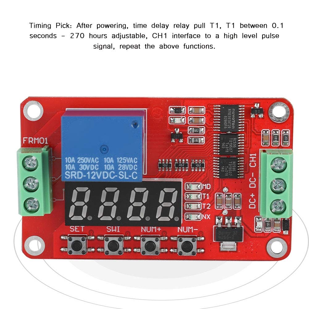
Image 5.1: Illustration of the Timing Pick mode, where the relay energizes for time T1 after power-on or a CH1 pulse.
5.2 Timing Pull Off Again Mode
Upon power-up, the relay remains de-energized. After a delay of T1, the relay energizes. It then remains energized for a duration of T2 before de-energizing again. A high-level pulse on the CH1 interface will restart this sequence.

Image 5.2: Illustration of the Timing Pull Off Again mode, showing T1 delay before energizing, and T2 duration for energization.
5.3 Infinite Loop Timing Mode 1/2
After power-up, the relay remains de-energized. After a delay of T1, the relay energizes. It then remains energized for a duration of T2 before de-energizing. This cycle (T1 delay, T2 energized) repeats indefinitely. A high-level pulse on the CH1 interface can restart the entire loop.

Image 5.3: Timing diagram illustrating the infinite loop timing mode, showing repetitive T1 (off) and T2 (on) cycles.
5.4 Latching/Relay Modes
A high-level pulse on the CH1 interface will energize the relay. A subsequent high-level pulse on CH1 will de-energize the relay. This mode acts as a toggle switch.
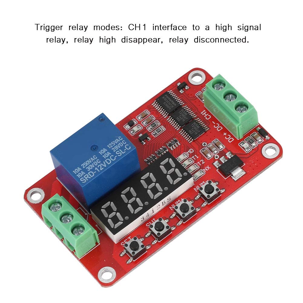
Image 5.4: Illustration of trigger relay modes, where a CH1 pulse toggles the relay state.
5.5 Pull/The Timing Mode
When the module is powered, the relay remains de-energized. A high-level pulse on the CH1 interface will energize the relay for a duration of T1. After T1 expires, the relay de-energizes. Subsequent high-level pulses on CH1 will repeat this function.
6. Programación y configuración
The FRM01 module is configured using the onboard buttons: COLOCAR, ISL, NÚMERO+, y NUM-. The display shows the current mode and timing parameters (T1, T2).
6.1 Funciones de los botones:
- CONJUNTO: Enters programming mode, confirms selections, and saves settings.
- SWI: Switches between different parameters (e.g., T1, T2, operating mode) within programming mode.
- NUM+: Increases the value of the currently selected parameter.
- NUM-: Decreases the value of the currently selected parameter.
6.2 General Programming Steps:
- Ingrese al modo de programación: Mantenga pulsado el COLOCAR button for a few seconds until the display changes, indicating entry into programming mode.
- Seleccione el modo de funcionamiento: Usar NÚMERO+ or NUM- to cycle through the available operating modes. The display will typically show a code representing the mode (e.g., P-1, P-2, etc.). Refer to the product documentation for specific mode codes.
- Modo de confirmación: Prensa COLOCAR to confirm the desired operating mode.
- Adjust Timing Parameters (T1, T2): After selecting the mode, the display will show T1. Use NÚMERO+ y NUM- Para ajustar su valor, presione ISL to switch to T2 (if applicable for the selected mode) and adjust its value.
- Set Time Unit: Some modes may allow setting the time unit (seconds, minutes, hours). Use ISL to cycle through units and NÚMERO+/NUM- Para seleccionar.
- Guardar y Salir: Mantenga pulsado COLOCAR again to save all settings and exit programming mode. The module will then operate according to the new configuration.
Note: Specific mode codes and parameter sequences may vary. It is recommended to refer to the detailed programming guide provided with the product for precise instructions.
7. Mantenimiento
The FRM01 module is designed for reliable operation with minimal maintenance. Follow these guidelines to ensure its longevity:
- Manténlo limpio: Periodically clean the module with a soft, dry cloth to remove dust and debris. Do not use liquid cleaners or solvents.
- Protección ambiental: Ensure the module is protected from excessive moisture, corrosive gases, and extreme temperatures.
- Integridad de la conexión: Revise periódicamente todas las conexiones del cableado para asegurarse de que permanezcan seguras y libres de corrosión.
- Evite el estrés físico: Do not subject the module to excessive vibration or mechanical shock.
8. Solución de problemas
If you encounter issues with your FRM01 module, refer to the following common problems and solutions:
| Problema | Posible causa | Solución |
|---|---|---|
| El módulo no se enciende. | Voltaje de fuente de alimentación incorrectotage or polarity. Loose power connections. | Verify DC 12V power supply. Check polarity (DC+ to +, DC- to -). Ensure connections are secure. |
| Relay does not activate/deactivate as expected. | Incorrect operating mode selected. Incorrect T1/T2 settings. Faulty CH1 input signal. | Review programming steps and ensure the correct mode and timing parameters are set. Verify the CH1 input signal is within the 3V-30V range and is a valid pulse. |
| Module is "stuck" in a specific state (e.g., T2 mode). | Programming error or internal state issue. | Try resetting the module by disconnecting and reconnecting power. Re-enter programming mode and reconfigure the desired settings. |
| Load is not controlled by the relay. | Incorrect load wiring (NO/NC/COM). Load exceeds relay current rating. | Check load wiring against the diagram (Image 4.1). Ensure the load's current draw does not exceed 10A. |
| Display is blank or shows erratic characters. | Power supply issue. Internal fault. | Check power supply. If the issue persists, the module may be faulty. |
| Difficulty understanding programming. | Lack of clear instructions. | Refer to the detailed programming steps in Section 6.2. Practice adjusting values with the buttons. Buscar additional online resources or videos if available. |
9. Garantía y soporte
For information regarding warranty coverage and technical support for your Zerone FRM01 module, please refer to the documentation provided at the time of purchase or contact your vendor directly. Keep your purchase receipt as proof of purchase.