
Docooler XUH6362338938855GM
Docooler JINGSHA X99-8D3 Motherboard User Manual
Model: XUH6362338938855GM
1. Introducción y másview
The Docooler JINGSHA X99-8D3 is a high-performance ATX gaming motherboard designed for LGA2011 V3 processors. It features four-channel DDR3 memory support, an M.2 NVME slot for high-speed storage, and multiple PCI-E expansion slots, making it suitable for demanding computing tasks and gaming setups. This manual will guide you through the installation, configuration, and maintenance of your motherboard.
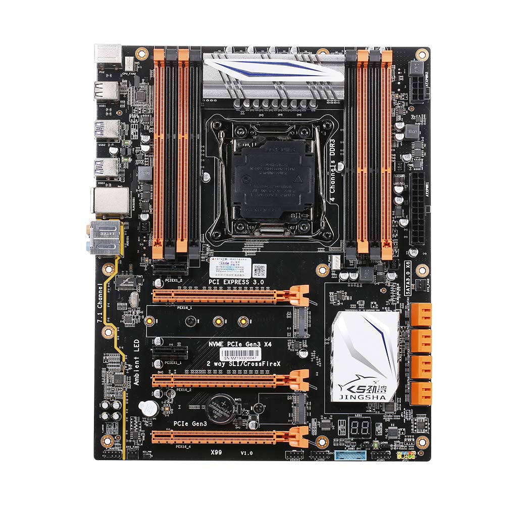
Figura 1.1: De arriba hacia abajo view of the Docooler JINGSHA X99-8D3 Motherboard, showcasing its layout with CPU socket, RAM slots, and various expansion slots.
2. Características principales
- M.2 NVME Support: Equipped with an M.2 hard disk port, supporting high-speed PCI-E NVME X4 for optimal operating system and application driver performance.
- Quad-Channel DDR3 Memory: Features 8 DDR3 memory slots across 4 channels, significantly improving capacity and performance, supporting up to 256GB.
- Digital Diagnostic Card: Integrated digital diagnostic card automatically tests hardware devices to ensure proper operation and assist in troubleshooting.
- Multiple PCI-E Expansion Slots: Provides 3 PCI-E expanded slots, configurable as X16/X8 to handle various workloads and multi-GPU setups.
- Construcción duradera: Built with a 10-layer PCB and high-quality capacitors for enhanced stability and heat resistance.

Figure 2.1: Diagram illustrating the six core technologies and features of the motherboard, including 4-channel DDR3*8, M.2 hard disk interface, digital diagnostic card, 7.1 channel audio, SATA3.0*8 interface, and Crossfire support.
3. Contenido del paquete
Verifique que todos los artículos enumerados a continuación estén presentes en su paquete:
- 1x Docooler JINGSHA X99-8D3 Motherboard
- 1x cable SATA
- 1x I/O Baffle (Backplate)
- 1x CPU Fan Board
- A bag of screws
4. Especificaciones
| Característica | Especificación |
|---|---|
| Modelo | X99-8D3 |
| Factor de forma | ATX |
| Graphic Slot | PCIE3.0 16X*3 |
| Tarjeta de red | tarjeta de red gigabit |
| Canal de audio | Canal 7.1 |
| CPU Type Support | LGA2011 V3 (2629V3/2649V3/2669V3/2678V3/2696V3/2676V3/2673V3) |
| Capas de PCB | 10 capas |
| ranura de memoria | DDR3*8 |
| Capacidad máxima de memoria | 256 GB |
| Interfaz SATA | SATA3.0*8, M.2 NVME |
| Interfaz PS/2 | Ratón / Teclado |
| Fuente de alimentación | 8 PIN*1, 24 PIN*1 |
| Interfaz USB | USB 3.0*6, USB 2.0*6 |
| Interfaz ampliada | PCIE 1X*2, M.2 WIFI*1 |
| Tamaño del artículo | 30.2 x 24.4 cm (11.89 x 9.61 pulgadas) |
| Peso del artículo | 930.5 g (32.82 onzas) |

Figura 4.1: detallada view of the motherboard's rear I/O panel, showing PS/2 ports, USB 2.0, USB 3.0, Gigabit Network Port, and 7.1 Audio Ports.
5. Configuración e instalación
Antes de comenzar la instalación, asegúrese de que el sistema esté apagado y desenchufado. Sujete la placa base por los bordes para evitar descargas estáticas.
5.1 Instalación de la CPU
- Locate the LGA2011 V3 CPU socket on the motherboard.
- Gently push down the CPU retention lever and swing it open.
- Alinee la marca triangular de la CPU con la marca correspondiente del zócalo. Coloque la CPU en el zócalo con cuidado, sin forzarla.
- Cierre la palanca de retención para asegurar la CPU.
- Aplique una capa fina y uniforme de pasta térmica en la parte superior de la CPU.
- Instale el enfriador de la CPU de acuerdo con las instrucciones del fabricante, asegurando el contacto y la presión adecuados.

Figura 5.1: Primer plano view of the LGA2011 V3 CPU socket on the motherboard, ready for CPU installation.
5.2 Installing RAM Modules
- Abra los clips en ambos extremos de las ranuras de memoria DDR3.
- Alinee la muesca del módulo RAM con la llave en la ranura de memoria.
- Presione firmemente ambos extremos del módulo RAM hasta que los clips encajen en su lugar, asegurando el módulo.
- For optimal performance, install RAM modules in matching pairs across the four channels as indicated in the motherboard manual or silkscreen.

Figura 5.2: View of the eight DDR3 RAM slots on the motherboard, showing their arrangement for quad-channel memory configuration.
5.3 Installing Storage Devices (M.2 NVME & SATA)
- M.2 NVME SSD: Localice la ranura M.2. Inserte el SSD M.2 en ángulo en la ranura, presiónelo suavemente hacia abajo y fíjelo con el tornillo incluido.
- Unidades SATA: Connect your SATA SSDs or HDDs to the SATA 3.0 ports using SATA data cables. Ensure the power supply SATA power connectors are also attached to the drives.

Figure 5.3: Close-up of the M.2 interface on the motherboard, highlighting its position and the PCI-E Gen3 X4 connection for high-speed data transfer.
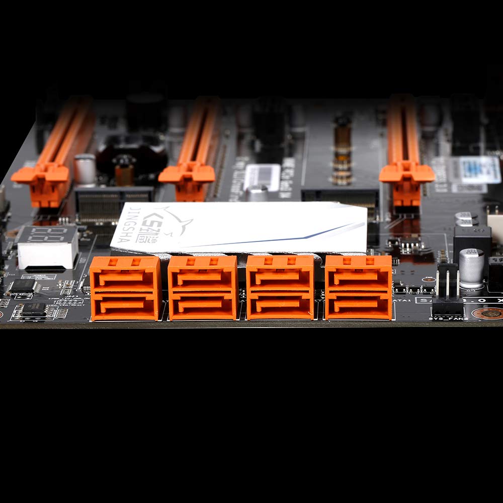
Figura 5.4: View of the eight orange SATA 3.0 ports on the motherboard, providing ample connectivity for storage devices.
5.4 Conexión de la fuente de alimentación
- Connect the 24-pin ATX power connector from your power supply unit (PSU) to the corresponding port on the motherboard.
- Connect the 8-pin CPU power connector (EPS12V) from your PSU to the 8-pin port near the CPU socket.
5.5 Installing Expansion Cards (PCIe)
- Locate the desired PCI-E 3.0 x16 or x1 slots.
- Retire la cubierta de la ranura de expansión correspondiente de la carcasa de su PC.
- Align the expansion card with the slot and press down firmly until it is fully seated. Secure the card with a screw to the case.

Figura 5.5: Angulado view of the motherboard, highlighting the three PCI Express 3.0 x16 slots and the smaller PCIe x1 slots, ready for graphics cards and other expansion cards.
6. Funcionamiento de la placa base
6.1 Primer arranque y configuración del BIOS
- Después de ensamblar todos los componentes, conecte el monitor, el teclado y el mouse.
- Power on your system. During the initial boot sequence, repeatedly press the DEL or F2 key (common for JINGSHA motherboards) to enter the BIOS/UEFI setup utility.
- En el BIOS, verifique que todos los componentes instalados (CPU, RAM, almacenamiento) se detecten correctamente.
- Configure el orden de arranque para priorizar el medio de instalación de su sistema operativo (unidad USB o DVD).
- Save changes and exit BIOS. The system will restart.
6.2 Instalación del sistema operativo
Follow the instructions provided with your operating system (e.g., Windows, Linux) to complete the installation process. Ensure you install all necessary drivers for the motherboard's chipsets, network, audio, and other components from the manufacturer's website or included driver disc.
7. Mantenimiento
Un mantenimiento adecuado garantiza la longevidad y el funcionamiento estable de su placa base.
- Eliminación de polvo: Limpie regularmente el polvo de la placa base y los componentes con aire comprimido. Asegúrese de que el sistema esté apagado y desenchufado antes de limpiarlo.
- Actualizaciones del BIOS: Periodically check the Docooler or JINGSHA official website for BIOS updates. BIOS updates can improve compatibility, stability, and performance. Follow update instructions carefully to avoid damaging the motherboard.
- Actualizaciones de controladores: Mantenga los controladores de su sistema actualizados para garantizar un rendimiento óptimo y compatibilidad con nuevo software y hardware.
- Condiciones ambientales: Operate the motherboard in a well-ventilated environment with stable temperature and humidity to prevent overheating and component degradation.
8. Solución de problemas
Esta sección aborda problemas comunes que podrías encontrar.
8.1 Sin energía/sin arranque
- Ensure the 24-pin ATX and 8-pin CPU power connectors are securely plugged into the motherboard.
- Check if the power supply unit (PSU) is switched on and connected to a working power outlet.
- Verify that the front panel power button cable is correctly connected to the motherboard's header.
8.2 No hay salida de pantalla
- Ensure your graphics card (if dedicated) is properly seated in its PCI-E slot and has all necessary power cables connected.
- Check that your monitor cable is securely connected to the graphics card or motherboard (if integrated graphics are used, though X99 typically requires a dedicated GPU).
- Try reseating your RAM modules. Incorrectly seated RAM is a common cause of no display.
8.3 POST Code Display (Digital Diagnostic Card)
The motherboard is equipped with a digital diagnostic card (POST code display) that shows a two-digit code during boot-up. Refer to the motherboard's detailed technical documentation (often available on the manufacturer's website) for a list of POST codes and their meanings. This can help pinpoint the exact component causing a boot failure.

Figura 8.1: Primer plano view showing the integrated digital diagnostic card (POST code display) on the motherboard, which assists in identifying hardware issues during boot.
9. Garantía y soporte
For warranty information and technical support, please refer to the documentation provided with your purchase or visit the official Docooler or JINGSHA webSitio. Conserve su comprobante de compra para reclamaciones de garantía.
Ask a question about this manual
Ask about setup, troubleshooting, compatibility, parts, safety, or missing instructions. Manuals+ will review the question and use this page’s manual context to help answer it.