
1. Introducción
This instruction manual provides essential information for the safe and efficient installation, operation, and maintenance of the Uponor Vario M Flow Meter Manifold, Model 1085950. Please read this manual thoroughly before installation and keep it for future reference. This product is designed for use in heating systems, particularly underfloor heating applications.
2. Información de seguridad
- La instalación y el mantenimiento sólo deben ser realizados por personal calificado de acuerdo con las normas y regulaciones locales.
- Ensure the system is depressurized and cooled before performing any work on the manifold.
- Utilice equipo de protección personal (EPP) adecuado durante la instalación y el mantenimiento.
- Do not exceed the specified maximum operating pressure (6 bar) or temperature (60 °C).
- Check all connections for leaks after installation and commissioning.
3. Producto terminadoview
The Uponor Vario M Flow Meter Manifold (Model 1085950) is an 8-output collector designed for precise control and distribution of heating water in underfloor heating systems. It features integrated flow meters for each circuit, allowing for individual flow adjustment and monitoring.
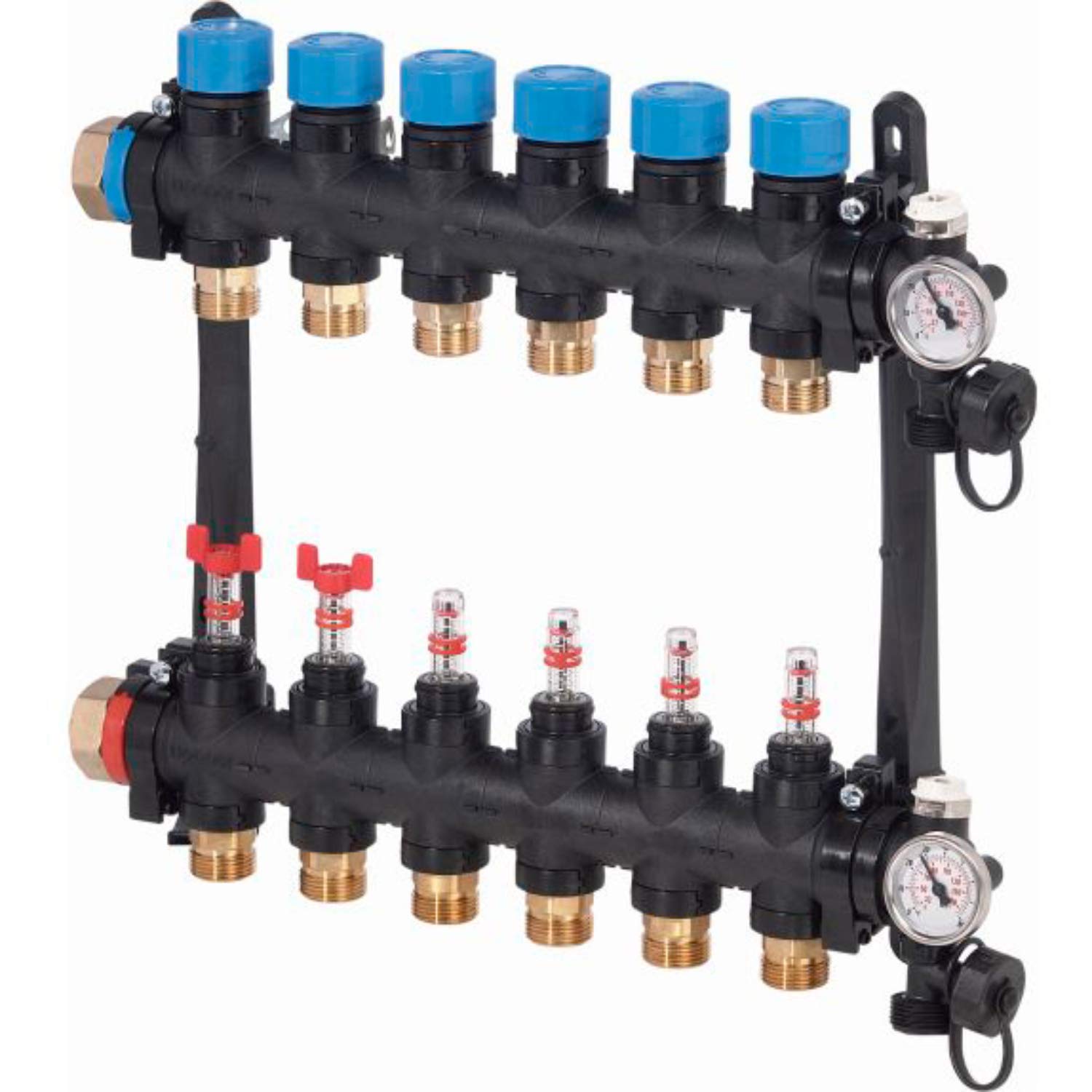
Image showing the Uponor Vario M Flow Meter Manifold with 8 outlets, featuring flow meters on the top bar and connection points below.
Componentes:
- Manifold body (reinforced polyamide)
- 8 Flow meters (integrated)
- Soportes de montaje
- Termómetros
- Flushers
- Tapones de drenaje
- G3/4" Eurocone threaded connections for heating circuits
- G1 main connection (right or left) with sealing gasket
4. Configuración e instalación
- Montaje: Securely attach the manifold to a suitable wall or mounting surface using the provided brackets. Ensure it is level and easily accessible for connections and adjustments.
- Conexión principal: Connect the main supply and return lines to the G1 connections on the manifold. Ensure a tight seal using the provided gasket. The manifold supports both right and left main connections.
- Conexiones del circuito: Connect the individual heating circuits to the 8 G3/4" Eurocone threaded outlets. Use appropriate fittings and ensure all connections are leak-free. The circuit separation is 50 mm.
- Lavado y llenado: Before commissioning, flush the system thoroughly to remove air and debris. Fill the system with water and vent any remaining air.
- Prueba de presión: Perform a pressure test according to local regulations to ensure system integrity.
5. Instrucciones de funcionamiento
- Ajuste de flujo: Each circuit is equipped with an integrated flow meter. To adjust the flow rate for a specific circuit, rotate the adjustment cap on the flow meter until the desired flow (indicated in liters per minute) is achieved.
- Monitoreo de temperatura: The integrated thermometers provide a visual indication of the supply and return temperatures.
- System Balancing: Adjust the flow meters on each circuit to balance the heating system, ensuring even heat distribution across all zones.
6. Mantenimiento
- Inspección regular: Periodically inspect the manifold and all connections for any signs of leaks, corrosion, or damage.
- Limpieza: Clean the exterior of the manifold with a soft, damp Paño. No utilice limpiadores abrasivos ni disolventes.
- Comprobación del medidor de flujo: Ensure flow meters are operating freely and accurately. If a flow meter becomes stuck or provides inconsistent readings, it may require cleaning or replacement by a qualified technician.
- Enrojecimiento: The system should be flushed periodically as part of general heating system maintenance to remove sludge and maintain efficiency. Use the integrated flushers and drain plugs for this purpose.
7. Solución de problemas
| Problema | Posible causa | Solución |
|---|---|---|
| No flow or low flow in a circuit | Air in the circuit, closed valve, clogged flow meter, pump issue | Bleed air from the circuit, check valve position, inspect/clean flow meter, check pump operation. |
| Fugas en las conexiones | Loose connection, damaged gasket/seal, incorrect fitting | Tighten connections, replace damaged gaskets/seals, ensure correct fittings are used. |
| Inconsistent heating across zones | System imbalance, air in circuits | Adjust flow meters to balance the system, bleed air from all circuits. |
8. Especificaciones
| Característica | Detalle |
|---|---|
| Número de modelo | 1085950 |
| Fabricante | Uponor |
| Número de salidas | 8 |
| Conexiones de circuito | G3/4" Eurocone male thread |
| Conexión principal | G1 (right or left, with sealing gasket) |
| Circuit Separation | 50 milímetros |
| Material | Reinforced Polyamide (UNE-EN-1264) |
| Presión nominal | 6 barras |
| Temperatura máxima de funcionamiento | 60 °C |
| Dimensiones (L x An x Al) | 51 cm x 5 cm x 25 cm |
| Peso | 3 kilogramos |
| Color | Negro |
9. Garantía y soporte
Uponor products are manufactured to high-quality standards. For warranty information, please refer to the specific warranty terms provided with your purchase or visit the official Uponor website. For technical support, spare parts, or service inquiries, please contact your local Uponor distributor or customer service representative. Always provide the model number (1085950) when seeking support.