1. Introducción
The Sunshine DT-17N Digital Multimeter is a versatile and reliable tool designed for accurate electrical measurements. It is particularly suitable for phone repair technicians and general electronics work, capable of measuring various electrical parameters including voltage, current, resistance, capacitance, and temperature. Its compact design and user-friendly features make it an essential tool for diagnosing and repairing electronic devices.

Figure 1: The Sunshine DT-17N Digital Multimeter, demonstrating its compact size for portability.
2. Información de seguridad
To ensure safe operation and prevent damage to the meter, please read and follow all safety instructions carefully. This multimeter features double insulation protection for enhanced user safety.
- Always ensure the test leads are in good condition and properly connected before taking measurements.
- No aplicar voltage or current that exceeds the maximum rated values for each range.
- Never use the multimeter if it appears damaged or if the test leads are frayed.
- Tenga cuidado al trabajar con vol.tages superior a 30 V CA RMS, 42 V pico o 60 V CC, ya que representan un peligro de descarga eléctrica.
- Desconecte siempre la alimentación del circuito y descargue las baterías de alto voltaje.tagy condensadores antes de medir resistencia, continuidad o diodos.
- Reemplace la batería rápidamente cuando aparezca el indicador de batería baja para garantizar lecturas precisas.
3. Producto terminadoview
3.1 Componentes del multímetro

Figura 2: Frente view of the DT-17N Multimeter, highlighting its main display and controls.
3.2. Características de la pantalla
The DT-17N features a large LCD display with a backlight, ensuring clear readability in various lighting conditions.

Figure 3: The multimeter's LCD display with its backlight feature, improving visibility in low-light environments.
- Gran pantalla LCD: Provides clear numerical readings.
- Iluminar desde el fondo: Improves visibility in dark or low-light conditions. Activated by pressing and holding the HOLD button.
- Unidad de medida: Displays the appropriate unit (e.g., V, A, Ω, °C/°F).
- Estado de la batería: Indica el nivel actual de la batería.
- Automatic Polarity Display: Shows positive or negative polarity automatically.
3.3. Controls and Input Ports
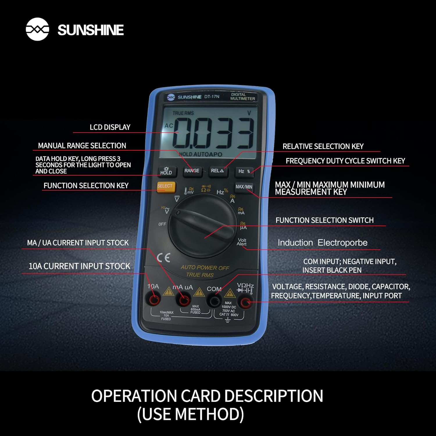
Figura 4: detallada view of the multimeter's controls and input ports with their respective functions.
- Interruptor de función giratorio: Se utiliza para seleccionar la función de medición deseada (por ejemplo, Voltage, Corriente, Resistencia, Temperatura).
- Botón SELECCIONAR: Alterna entre diferentes modos de medición dentro de una única posición del interruptor giratorio (por ejemplo, voltaje CA/CC)tage, Diodo/Continuidad).
- Botón ESPERA: Freezes the current reading on the display. Press and hold to activate/deactivate the backlight.
- Botón RANGO: Allows manual selection of measurement ranges, overriding the automatic ranging feature.
- RELA Button (Relative Selection Key): Mide la diferencia entre un valor de referencia almacenado y la lectura actual.
- Hz % Button (Frequency Duty Cycle Switch Key): Alterna entre mediciones de frecuencia y ciclo de trabajo.
- Botón MÁX./MÍN.: Displays the maximum or minimum measured value during a measurement session.
- Puerto de entrada VΩHz: Conecte el cable de prueba rojo para vol.tage, mediciones de resistencia, frecuencia, capacitancia, diodos y temperatura.
- Puerto de entrada COM: Connect the black test lead (common ground) for all measurements.
- mA/uA Input Port: Connect the red test lead for measuring small currents (milliamperes and microamperes).
- 10A Input Port: Connect the red test lead for measuring large currents (up to 10 Amperes).
- Volt Alert (NCV): Vol sin contactotagFunción de detección electrónica.
4. Configuración
4.1. Instalación de la batería
The DT-17N is battery-powered. To install or replace the battery:
- Asegúrese de que el multímetro esté apagado.
- Localice la tapa del compartimiento de la batería en la parte posterior de la unidad.
- Desatornille el/los tornillo(s) de retención y retire la cubierta.
- Insert the new battery, observing correct polarity (+ and -).
- Vuelva a colocar la tapa del compartimiento de la batería y fíjela con el/los tornillo(s).
4.2. Conexión de los cables de prueba
Always connect the black test lead to the COM input jack. Connect the red test lead to the appropriate input jack based on the measurement you intend to perform:
- para vol.tage, Resistance, Capacitance, Frequency, Diode, and Temperature measurements: Connect the red test lead to the VΩHz Jacobo.
- For Current measurements (mA/uA): Connect the red test lead to the mA/uA Jacobo.
- For High Current measurements (10A): Connect the red test lead to the 10A Jacobo.
5. Instrucciones de funcionamiento
The Sunshine DT-17N features automatic identification for most ranges, simplifying operation. Use the rotary switch to select the primary function and the SELECT button to toggle sub-functions.
5.1. Medición del volumentage (CA/CC)
- Gire el interruptor giratorio a la V posición.
- Si es necesario, presione el SELECCIONAR button to toggle between AC (~) and DC (—) voltage.
- Conecte el cable de prueba negro al COM Jack y el cable de prueba rojo a la VΩHz Jacobo.
- Conecte las sondas de prueba en paralelo al circuito o componente que desea medir.
- Leer el vol.tage valor en la pantalla.

Figure 5: The multimeter showing a DC millivolt measurement on its display.
5.2. Medición de corriente (CA/CC)
Precaución: Never connect the multimeter in parallel when measuring current, as this can damage the meter and the circuit. Always connect in series.
- Gire el interruptor giratorio a la mA/uA or 10A posición, dependiendo de la corriente esperada.
- Si es necesario, presione el SELECCIONAR button to toggle between AC (~) and DC (—) current.
- Conecte el cable de prueba negro al COM Conecte el cable de prueba rojo a la mA/uA or 10A jack accordingly.
- Abra el circuito y conecte las sondas de prueba en serie con la carga.
- Lea el valor actual en la pantalla.
5.3. Medición de resistencia
- Gire el interruptor giratorio a la Ω posición.
- Conecte el cable de prueba negro al COM Jack y el cable de prueba rojo a la VΩHz Jacobo.
- Asegúrese de que el circuito esté desenergizado y que todos los capacitores estén descargados.
- Conecte las sondas de prueba a través del componente para medir su resistencia.
- Lea el valor de resistencia en la pantalla.
5.4. Medición de capacitancia
- Gire el interruptor giratorio a la Capacidad symbol (often shared with diode/continuity).
- Presione el SELECCIONAR button until the capacitance mode is active.
- Conecte el cable de prueba negro al COM Jack y el cable de prueba rojo a la VΩHz Jacobo.
- Asegúrese de que el capacitor esté completamente descargado antes de conectar las sondas de prueba.
- Conecte las sondas de prueba a través del condensador.
- Lea el valor de capacitancia en la pantalla.
5.5. Measuring Frequency / Duty Cycle
- Gire el interruptor giratorio a la Hz% posición.
- Presione el Hz% Botón para alternar entre frecuencia (Hz) y ciclo de trabajo (%).
- Conecte el cable de prueba negro al COM Jack y el cable de prueba rojo a la VΩHz Jacobo.
- Conecte las sondas de prueba en paralelo a la fuente de señal.
- Lea el valor de frecuencia o ciclo de trabajo en la pantalla.
5.6. Medición de temperatura
The DT-17N can measure temperature using a K-type thermocouple (not always included, check package contents).

Figura 6: Example of temperature measurement using the DT-17N Multimeter with a thermocouple.
- Gire el interruptor giratorio a la ° C / ° F posición.
- Si es necesario, presione el SELECCIONAR button to choose between Celsius or Fahrenheit.
- Conecte el termopar tipo K a la VΩHz y COM tomas, observando la polaridad.
- Place the thermocouple tip on or in the object whose temperature you wish to measure.
- Lea el valor de la temperatura en la pantalla.
5.7. Prueba de diodos y continuidad
- Gire el interruptor giratorio a la Diodo/Continuidad símbolo.
- Presione el SELECCIONAR Botón para alternar entre prueba de diodo y prueba de continuidad.
- Conecte el cable de prueba negro al COM Jack y el cable de prueba rojo a la VΩHz Jacobo.
- Para la prueba de diodos: Conecte las sondas a través del diodo. La pantalla mostrará el voltaje directo.tage gota. Invierta las sondas para comprobar si hay circuito abierto.
- For Continuity Test: Connect the probes across the circuit or component. A beep indicates continuity (low resistance).
5.8. Vol sin contactotagDetección de e (NCV)
The NCV function allows detection of AC voltage sin contacto directo con los conductores.
- Gire el interruptor giratorio a la SIN VALOR COMERCIAL position (often indicated by a Volt Alert symbol).
- Move the top part of the multimeter near the conductor.
- The meter will beep and/or flash an indicator light if AC voltagSe detecta e.
5.9. Retención de datos y retroiluminación
- Retención de datos: Presione el SOSTENER Presione brevemente el botón para congelar la lectura actual en la pantalla. Presione nuevamente para liberar.
- Iluminar desde el fondo: Mantenga pulsado el SOSTENER Botón durante aproximadamente 3 segundos para encender o apagar la luz de fondo de la pantalla.
5.10. Medición MÁX/MÍN
This function records the maximum and minimum values measured during a session.
- Seleccione la función de medición deseada (por ejemplo, Voltagmi).
- Presione el MÁXIMO/MÍNIMO button. The display will show 'MAX' and the maximum value recorded.
- Prensa MÁXIMO/MÍNIMO again to cycle to 'MIN' and view the minimum value.
- Mantenga pulsado MÁXIMO/MÍNIMO para salir de este modo.
6. Mantenimiento
Un mantenimiento adecuado garantiza la longevidad y precisión de su multímetro.
6.1. Limpieza
Limpiar la carcasa con publicidadamp Paño y detergente suave. No utilice abrasivos ni disolventes. Asegúrese de que el medidor esté completamente seco antes de usarlo.
6.2. Reemplazo de la batería
Refer to Section 4.1 for battery replacement instructions. Always use the specified battery type.
6.3. Holster Care
The multimeter is protected by a thick rubber shockproof holster, designed for durability and a non-slip grip. Keep the holster clean and free from debris.

Figure 7: The durable rubber holster provides protection and a comfortable grip for the multimeter.
7. Solución de problemas
If you encounter issues with your DT-17N multimeter, refer to the table below for common problems and solutions.
| Problema | Posible causa | Solución |
|---|---|---|
| Sin pantalla o pantalla tenue | Low or dead battery; Poor battery contact | Replace battery; Check battery contacts |
| Lecturas incorrectas | Wrong function selected; Improper test lead connection; Damaged test leads; Out of range | Select correct function; Ensure leads are in correct jacks; Replace leads; Select higher range or check specifications |
| No hay pitido de continuidad | Circuit resistance too high; Continuity mode not selected | Ensure resistance is below threshold; Press SELECT to enter continuity mode |
| Fuse blown (for current measurements) | Overcurrent applied | Replace fuse with specified type and rating; Ensure correct current measurement procedure |
8. Especificaciones
Technical specifications for the Sunshine DT-17N Digital Multimeter.
| Característica | Especificación |
|---|---|
| Modelo | DT-17N |
| Tipo de medida | Multímetro |
| Mostrar | 5999 (5 5/6) counts, Automatic Polarity Display, Backlit LCD |
| Samptasa de ling | Aproximadamente 3 veces por segundo |
| Fuente de poder | Funciona con pilas |
| Vol. Mínimo de funcionamientotage | 3 voltios (CC) |
| Rango de medición de temperatura | 0 °C a 1000 °C (32 °F a 1832 °F) |
| Induction Electroprobe Function | Yes (NCV) |
| Conversión A / D integral doble | Sí |
| Dimensiones del artículo | 5.51 x 2.76 x 1.18 pulgadas |
| Peso del artículo | 0.55 kilogramos |
| Color | Azul |
9. Garantía y soporte
9.1. Información de garantía
This product comes with a warranty of 3 meses desde la fecha de compraConserve su comprobante de compra para reclamaciones de garantía. La garantía cubre defectos de fabricación en condiciones normales de uso.
9.2. Atención al cliente
For technical assistance or inquiries regarding your Sunshine DT-17N Digital Multimeter, please contact your retailer or the manufacturer's customer service department. Refer to your purchase documentation for specific contact details.


