
1. Introducción
This manual provides detailed instructions for the installation, operation, and maintenance of the QIACHIP Mini Wireless Remote Control Switch. This device is designed to provide wireless control for various DC applications, including LED lights, car batteries, and door locks, operating within a voltagRango de CC de 6 V a 60 V.

Figure 1: QIACHIP Mini Wireless Remote Control Switch (1 Receiver + 1 Transmitter)
2. Producto terminadoview
Características principales:
- Amplio Voltage Rango: Vol de entradatage DC 5V-60V, supporting various DC applications.
- Alta capacidad de corriente: Maximum relay contact current of 20 Amps.
- Frecuencia RF: Operates on 433 MHz for reliable wireless communication.
- Distancia de transmisión extendida: Approximately 50-100m in open spaces. The antenna can be extended for improved reception.
- Múltiples modos de funcionamiento: Supports Momentary, Toggle, Latched, and Delay modes.
- Compatibilidad de control remoto: Supports EV1527 learning code remote controllers, allowing pairing with up to 20 remotes.
- Diseño compacto: PCB size of 47 x 26 x 18 mm (L, W, H).
- Aplicaciones versátiles: Suitable for car battery power control, garage doors, electronic doors, appliances, motorcycle alarms, car sunroofs, and heating systems.

Figure 2: Product application examples for lighting control.

Figure 3: Enhanced features of the remote switch, including an exposed antenna for better reception and a wider voltage rango.
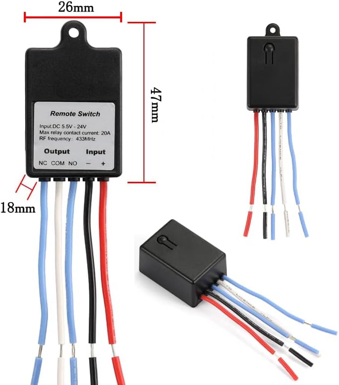
Figure 4: Physical dimensions of the remote control switch.

Figure 5: Internal components and terminal labels of the remote switch.
3. Especificaciones
| Especificación | Valor |
|---|---|
| Modo de operación | ENCENDIDO APAGADO |
| Calificación actual | 20 Amps |
| Vol de funcionamientotage | CC 5 V-60 V |
| Tipo de contacto | Normalmente abierto (NO), normalmente cerrado (NC), común (COM) |
| Tipo de conector | Inalámbrico |
| Terminal | Soldar |
| Dimensiones del artículo (largo x ancho x alto) | 1.85 x 1.02 x 0.71 pulgadas (47 x 26 x 18 mm) |
| Tipo de circuito | 1 vías |
| Material de contacto | Plástico |
| Calificación de protección internacional | IP54 |
| Número de posiciones | 2 |
| Método de control | Remoto |
| Protocolo de conectividad | 433 MHz |
| Quétage | 480 vatios |
| Peso del artículo | 1.76 onzas |
| Baterías (Transmisor) | Se requiere 1 batería CR2032 (incluida) |
4. Instalación y cableado
The QIACHIP remote control switch features three output terminals: NC (normalmente cerrado), COM (común), y NO (Normalmente abierto). These terminals function like a Single-Pole Double-Throw (SPDT) switch. The input terminals are labeled + y - for DC power connection.
Wiring Principles:
- DE: This is the common terminal where the power source or load is typically connected.
- CAROLINA DEL NORTE: Normally Closed. This terminal is connected to COM by default when the relay is inactive.
- NO: Normally Open. This terminal is disconnected from COM by default when the relay is inactive. It connects to COM when the relay is activated.
- Input Power (+ and -): Connect your DC power supply (5V-60V) to these terminals to power the receiver module.
Diagramas de cableado típicos:

Figure 6: Wiring for a DC load (e.g., LED light). The load is connected to NO and COM, and the receiver is powered by the DC source.

Figure 7: Wiring for an access control or door lock system. The lock is connected to NO and COM, and the receiver is powered by the DC source.

Figure 8: Wiring for an external power supply load. The remote switch controls the load's circuit via NO and COM, while the load has its own power source.
Importante: Asegúrese siempre de que el volumen de la fuente de alimentacióntage matches the requirements of your load and the remote switch. Incorrect wiring can damage the device or connected components.
5. Operating Modes and Pairing Instructions
The QIACHIP remote control switch supports four operating modes: Momentary, Toggle, Latched, and Delay. Each mode offers different control behaviors. To change modes, you must first perform a reset. After the reset, all previously paired remote controls are temporarily deactivated.
Video: Wiring and Pairing Demonstration
Video 1: This video demonstrates the wiring process and how to pair the remote control switch in different operating modes (Momentary, Toggle, Latched, and Delay Off).
5.1. Modo momentáneo
In Momentary mode, the output is active only while the remote button is pressed. Releasing the button deactivates the output.
- Emparejamiento: Presione el botón de aprendizaje en el receptor una vez. The indicator light will turn on. Then, press any button on your remote control. The indicator light will flash and turn off, indicating successful pairing.

Figure 9: Momentary Mode operation.
5.2. Modo de alternar
In Toggle mode, pressing the remote button once activates the output, and pressing it again deactivates the output.
- Emparejamiento: Presione el botón de aprendizaje en el receptor dos veces. The indicator light will turn on. Then, press any button on your remote control. The indicator light will flash and turn off, indicating successful pairing.

Figure 10: Toggle Mode operation.
5.3. Modo bloqueado
In Latched mode, one remote button activates the output, and another remote button deactivates it. This mode requires a multi-button remote.
- Emparejamiento: Presione el botón de aprendizaje en el receptor tres veces. The indicator light will turn on. Then, press the first button (e.g., 'A') on your remote, followed by the second button (e.g., 'B'). The indicator light will flash and turn off, indicating successful pairing.

Figure 11: Latched Mode operation.
5.4. Delay Off Mode
In Delay Off mode, the output activates when the remote button is pressed and remains active for a set duration (e.g., 5, 10, 15, or 20 seconds) before automatically deactivating.
- Pairing for 5-second delay: Presione el botón de aprendizaje en el receptor cuatro veces. The indicator light will turn on. Then, press any button on your remote control. The indicator light will flash and turn off, indicating successful pairing.
- Pairing for 10-second delay: Presione el botón de aprendizaje en el receptor cinco veces.
- Pairing for 15-second delay: Presione el botón de aprendizaje en el receptor seis veces.
- Pairing for 20-second delay: Presione el botón de aprendizaje en el receptor siete veces.

Figure 12: Delay Off Mode operation.
5.5. Resetting All Paired Remotes
To clear all previously paired remote controls and reset the receiver to its default state, follow these steps:
- Presione el botón de aprendizaje en el receptor eight times. The indicator light will flash rapidly and then turn off. This indicates that all stored remote control data has been erased.
6. Mantenimiento
The QIACHIP Mini Wireless Remote Control Switch is designed for durability and requires minimal maintenance. Keep the device clean and free from dust and moisture. Ensure all wiring connections are secure to prevent intermittent operation. Replace the CR2032 battery in the transmitter when its range decreases or it stops responding.
7. Solución de problemas
- El dispositivo no responde al control remoto:
- Compruebe si la batería del control remoto está agotada. Reemplácela si es necesario.
- Ensure the receiver is powered correctly (DC 5V-60V).
- Verify that the remote is paired correctly to the receiver in the desired mode. If unsure, perform a reset and re-pair.
- Check for strong RF interference in the environment.
- Alcance reducido del control remoto:
- Reemplace la batería del control remoto.
- Ensure the receiver's antenna is not obstructed and is extended if possible.
- Minimize physical obstructions (walls, metal objects) between the remote and receiver.
- Output not activating/deactivating correctly:
- Verify wiring connections to NC, COM, and NO terminals are correct for your application.
- Ensure the load's power requirements do not exceed the relay's maximum contact current (20A) or wattagmi (480W).
- Confirm the operating mode is set as intended (Momentary, Toggle, Latched, Delay).
- Indicator light not functioning:
- Check the power supply to the receiver.
- If the device is otherwise functional, the indicator light may be faulty, but this does not affect core operation.
8. Garantía y soporte
For warranty information or technical support, please refer to the product packaging or contact QIACHIP customer service through the retailer where the product was purchased. Keep your purchase receipt for warranty claims.