
SeKi 17437
SeKi Network Cable Tester (Model 17437) - Instruction Manual
For RJ11, RJ12, and RJ45 Network and ISDN Cables
1. Introducción
The SeKi Network Cable Tester (Model 17437) is a versatile and reliable tool designed for verifying the integrity of network and ISDN cable connections. It supports universal compatibility with RJ11, RJ12, and RJ45 network connections, making it an essential device for IT technicians, system administrators, and DIY enthusiasts. This tester is particularly suitable for LAN network cables including CAT5, CAT6, and CAT7 standards.
The device consists of two units: a Master unit and a Remote unit. Both units feature integrated LED indicators for 8 individual wires plus a ground (G) indicator, providing clear visual feedback during testing. These test LEDs allow you to monitor the cable's wiring and quickly detect potential errors such as open circuits, short circuits, miswires, and cross-overs.
2. Instrucciones de seguridad
- Lea todas las instrucciones antes de operar el dispositivo.
- No exponga el dispositivo a la humedad ni a temperaturas extremas.
- Use only a 9V battery of the specified type. Ensure correct polarity during installation.
- Retire la batería si el dispositivo no se utilizará durante un período prolongado para evitar fugas.
- No intente abrir ni reparar el dispositivo usted mismo. Encargue cualquier reparación a personal cualificado.
- Mantenga el dispositivo fuera del alcance de los niños.
3. Componentes del producto
The SeKi Network Cable Tester comprises two main parts:
- Unidad maestra: The larger unit with the power switch and multiple ports.
- Unidad remota: The smaller, detachable unit used for testing the far end of a cable.
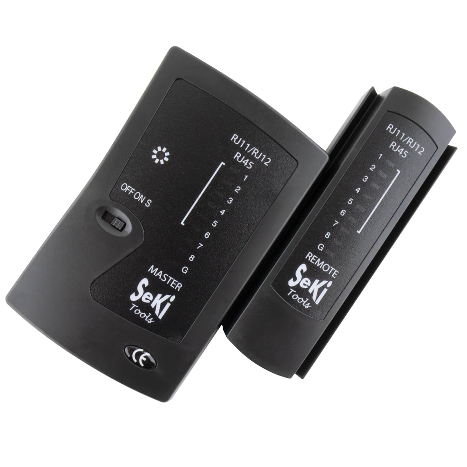
Image 1: The SeKi Network Cable Tester, showing both the Master and Remote units.
Master Unit Features:
- RJ11/RJ12/RJ45 Ports: For connecting various cable types.
- OFF/ON/S Switch: Power switch with two testing speeds (ON for normal, S for slow).
- Indicadores LED (1-8, G): Display the status of each wire and ground connection.
Remote Unit Features:
- RJ11/RJ12/RJ45 Port: For connecting the remote end of the cable.
- Indicadores LED (1-8, G): Mirror the Master unit's indicators for continuity.

Image 2: The Master and Remote units of the SeKi Network Cable Tester, shown separated.
4. Configuración
4.1 Instalación de la batería
- Localice el compartimiento de la batería en la parte posterior de la unidad principal.
- Abra la tapa de la batería.
- Insert a 9V battery (not included), ensuring correct polarity (+/-).
- Cierre bien la tapa de la batería.
4.2 Connecting Cables for Testing
Antes de realizar la prueba, asegúrese de que el cable esté desconectado de todos los dispositivos de red activos.
- For testing a patch cable (short cable): Connect one end of the cable to the appropriate port (RJ11, RJ12, or RJ45) on the Master unit and the other end to the corresponding port on the Remote unit.
- For testing an installed cable (e.g., wall jack to patch panel): Connect one end of the cable (or wall jack) to the Master unit and the other end (e.g., patch panel port) to the Remote unit.

Imagen 3: Primer plano view of the SeKi Network Cable Tester's RJ11, RJ12, and RJ45 ports.
5. Instrucciones de funcionamiento
5.1 Powering On and Test Modes
Once the cable is connected, slide the OFF/ON/S switch on the Master unit to your desired test mode:
- EN: This is the normal test speed. The LEDs will light up sequentially from 1 to 8, then G (Ground), indicating the continuity of each wire.
- S (Slow): This mode provides a slower test speed, allowing for more detailed observation of the LED sequence, which can be helpful for identifying subtle issues.
5.2 Interpretación de los indicadores LED
Observe the LED indicators on both the Master and Remote units. The LEDs on the Remote unit should mirror the sequence of the Master unit's LEDs.
- Correct Wiring (Pass): The LEDs on both units will light up in a sequential order (1-2-3-4-5-6-7-8-G). This indicates that all wires have proper continuity and are correctly mapped.
- Open Circuit / Broken Wire: If an LED on either unit fails to light up in the sequence, it indicates an open circuit or a broken wire for that specific pin.
- Cortocircuito: If two or more LEDs light up simultaneously or out of sequence, it indicates a short circuit between those wires.
- Miswire / Cross-over: If the sequence of LEDs on the Remote unit does not match the Master unit (e.g., Master shows 1-2-3, Remote shows 1-3-2), it indicates a miswire or cross-over.
- Ground (G) Indicator: The 'G' LED indicates the continuity of the ground wire.

Image 4: The SeKi Network Cable Tester in operation, connected to a blue network cable.
5.3 Testing Different Cable Types
- RJ45 Cables (8P8C): Used for LAN connections (Ethernet). The tester will check all 8 pins and the ground.
- RJ12 Cables (6P6C): Often used for telephone systems. The tester will check pins 1-6 and ground.
- RJ11 Cables (6P4C): Commonly used for telephone lines. The tester will check pins 1-4 and ground.
Always ensure you connect the cable to the correct port on both the Master and Remote units.
6. Mantenimiento
- Limpieza: Limpie el dispositivo con un paño suave y seco. No utilice limpiadores líquidos ni disolventes.
- Almacenamiento: Guarde el probador en un lugar fresco y seco, alejado de la luz solar directa y de temperaturas extremas.
- Batería: If the device will not be used for an extended period, remove the 9V battery to prevent potential leakage and damage to the unit.
7. Solución de problemas
- No LEDs light up:
- Compruebe que la batería de 9 V esté correctamente instalada y tenga suficiente carga. Reemplácela si es necesario.
- Ensure the power switch is in the 'ON' or 'S' position.
- Incorrect LED sequence or missing lights:
- Verify that the cable connectors are properly crimped and seated firmly in the tester's ports.
- Inspect the cable for visible damage (cuts, kinks).
- If testing an installed cable, check the wall jacks or patch panel connections.
- Intermittent test results:
- Ensure stable connections between the cable and the tester units.
- Check the battery charge. Low battery can cause inconsistent readings.
8. Especificaciones
| Número de modelo | 17437 |
| Dimensiones (L x An x Al) | 10.5 x 9.5 x 2.7 cm |
| Peso | 131 gramos |
| Conectores compatibles | RJ11 (6P4C), RJ12 (6P6C), RJ45 (8P8C) |
| Fuente de poder | 1 batería de 9 V (no incluida) |
| Tipos de cables admitidos | LAN (CAT5, CAT6, CAT7), ISDN |
| Color | Negro |
| Certificaciones | CE, REACH, RoHS |
9. Garantía y soporte
This product is designed for durability and reliability. Spare parts availability is typically 2 years from the date of purchase.
For technical support, warranty claims, or further assistance, please contact your retailer or the point of purchase. Ensure you have your proof of purchase and the product model number (17437) available when contacting support.
Ask a question about this manual
Ask about setup, troubleshooting, compatibility, parts, safety, or missing instructions. Manuals+ will review the question and use this page’s manual context to help answer it.