Vetroo AL800
Vetroo AL800 Mid Tower ATX PC Computer Case
Manual de instrucciones
Introducción
This manual provides detailed instructions for the assembly, operation, and maintenance of your Vetroo AL800 Mid Tower ATX PC Computer Case. Please read this manual thoroughly before beginning installation to ensure proper setup and optimal performance.

Figure 1: Vetroo AL800 Mid Tower ATX PC Computer Case (Black)
Información de seguridad
- Desconecte siempre la fuente de alimentación de la toma de pared antes de instalar o quitar cualquier componente.
- Handle components with care to avoid damage from electrostatic discharge. Consider using an anti-static wrist strap.
- Mantenga la carcasa y los componentes alejados de líquidos y humedad excesiva.
- Asegúrese de que haya una ventilación adecuada para evitar el sobrecalentamiento.
- No intente modificar la carcasa ni sus componentes, ya que esto puede anular la garantía y suponer riesgos de seguridad.
Contenido del paquete
Verifique que todos los artículos estén presentes en el paquete:
- Vetroo AL800 Mid Tower ATX PC Computer Case
- Accessory Box (screws, standoffs, cable ties)
- Pre-installed 1x 120mm PWM/ARGB Fan (rear)
- Manual de usuario (este documento)
Características principales
- ARGB LED Strip: Integrated LED lighting and ARGB case fans can be synchronized with compatible motherboards via a 5V 3-pin interface.
- Door Opening Design: Features a 4mm thick tempered glass side panel with a convenient door-opening mechanism for easy access to internal components.
- High Performance Airflow: A mesh front panel and strategically placed dust filters ensure optimal airflow and system cooling.
- Amplia compatibilidad: Supports ATX, M-ATX, and ITX motherboards. Accommodates GPUs up to 340mm in length and CPU coolers up to 165mm in height.
- Soporte de refrigeración líquida: Front panel supports up to a 360mm liquid cooling radiator.
- Soporte de los fans: Admite hasta 8 ventiladores de 120 mm.
- Gestión de cables sencilla: Includes two soft silicone cord grommets for organized cable routing.
- Powerful I/O Panel: Features 1x USB 3.2 Type-C port, 2x USB 3.0 ports, and a combined microphone/headphone jack.
Configuración e instalación
1. Preparación general
- Coloque el estuche sobre una superficie plana y estable.
- Open the tempered glass side panel by gently pulling it open. It is hinged for easy access.
- Remove the tempered glass panel if necessary for easier installation by lifting it off its hinges once open.

Figure 2: Tempered Glass Door Opening Design
2. Instalación de la placa base
- Instale el protector de E/S (si corresponde) en la abertura trasera de la carcasa.
- Align your ATX, M-ATX, or ITX motherboard with the pre-installed standoffs.
- Asegure la placa base utilizando los tornillos provistos en la caja de accesorios.
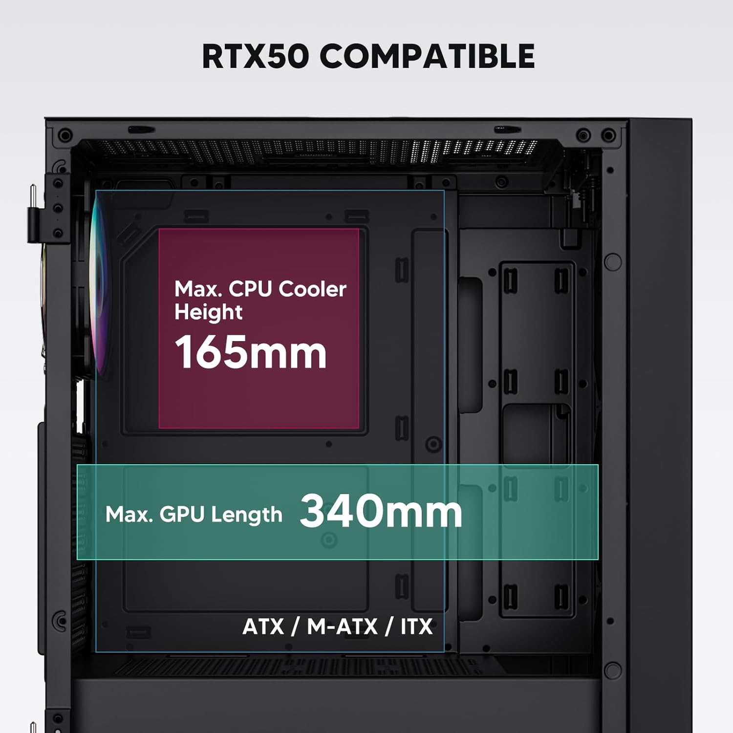
Figure 3: Motherboard and Component Clearance (Max CPU Cooler Height 165mm, Max GPU Length 340mm)
3. Storage Device Installation (HDD/SSD)
- Locate the dedicated mounting points for SSDs and HDDs.
- Install 2.5" SSDs onto the SSD trays or mounting brackets.
- Install 3.5" HDDs into the drive cage located at the bottom of the case.
- Asegure todas las unidades con los tornillos adecuados.

Figure 4: Internal Layout with Drive Bay Locations (SSD, HDD, Power Supply)
4. Instalación de la fuente de alimentación
- Mount your power supply unit (PSU) in the dedicated compartment at the bottom rear of the case.
- Ensure the PSU fan faces downwards (if the case has a bottom vent) or upwards, depending on your cooling preference.
- Secure the PSU with screws from the rear of the case. The case supports PSUs up to 200mm in length.
5. Instalación de la tarjeta de expansión (GPU)
- Retire las cubiertas de las ranuras PCI-E necesarias de la parte trasera de la carcasa.
- Insert your graphics card or other expansion cards into the motherboard's PCI-E slots.
- Fije las tarjetas con tornillos. La caja admite GPU de hasta 340 mm de longitud.
6. Cooling System Installation (Fans/Radiators)
- The case comes with one pre-installed 120mm PWM/ARGB fan at the rear.
- Additional fans (120mm or 140mm) can be installed at the front, top, and bottom.
- Liquid cooling radiators up to 360mm can be installed at the front, and up to 240mm at the top.
- Refer to the diagram for supported fan and radiator configurations.

Figure 5: Fan and Liquid Radiator Support Diagram
7. Conexiones del panel frontal
- Connect the front panel cables (Power, Reset, USB 3.0, USB Type-C, HD Audio) to the corresponding headers on your motherboard.
- Consult your motherboard manual for the exact pin layout of these headers.
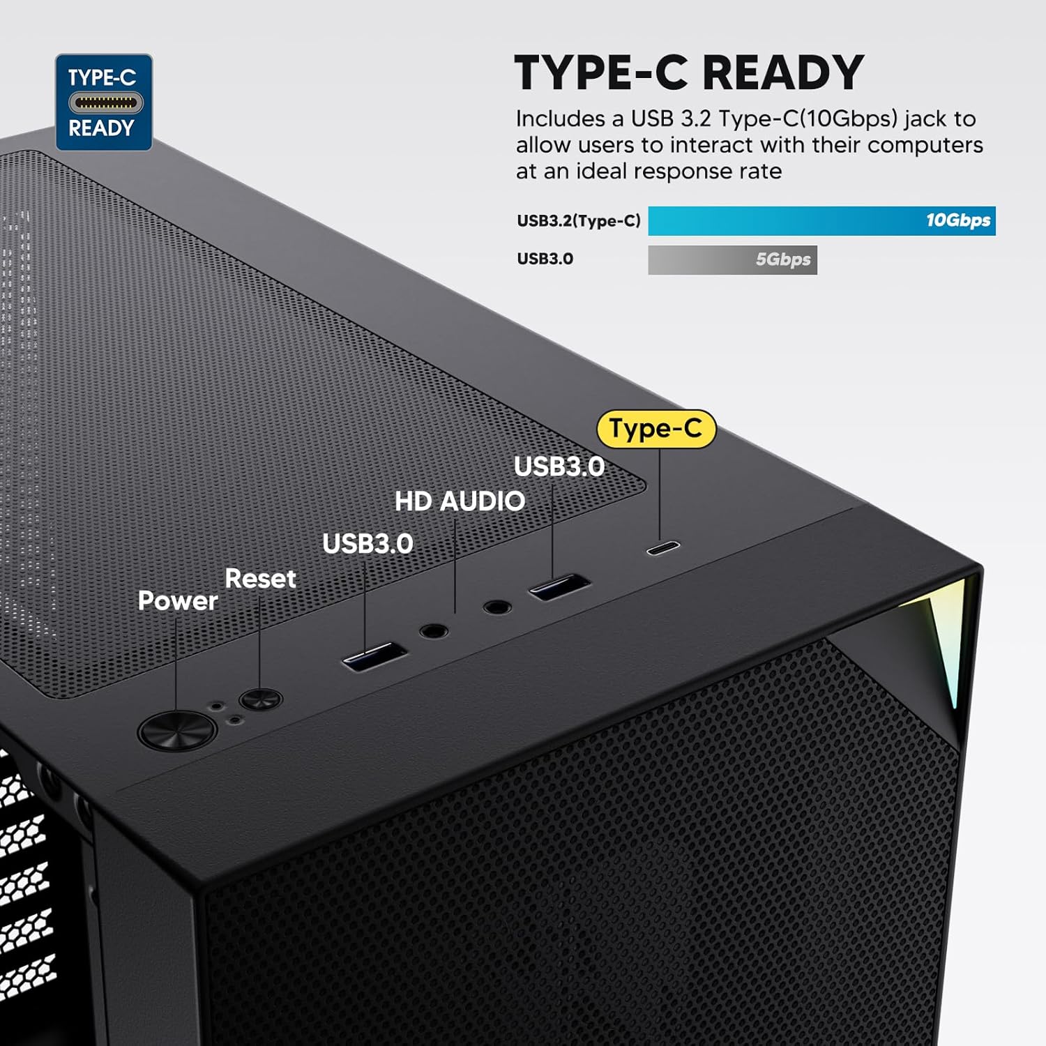
Figure 6: Top I/O Panel Connections
8. ARGB and PWM Connections
- The pre-installed fan and ARGB LED strip require connection to your motherboard.
- Connect the 4-pin PWM connector from the fan to a compatible fan header on your motherboard for speed control.
- Connect the 3-pin ARGB connector from the fan and LED strip to a 5V 3-pin ARGB header on your motherboard for lighting synchronization. No lo conecte a un encabezado RGB de 12 V, ya que esto dañará los LED.
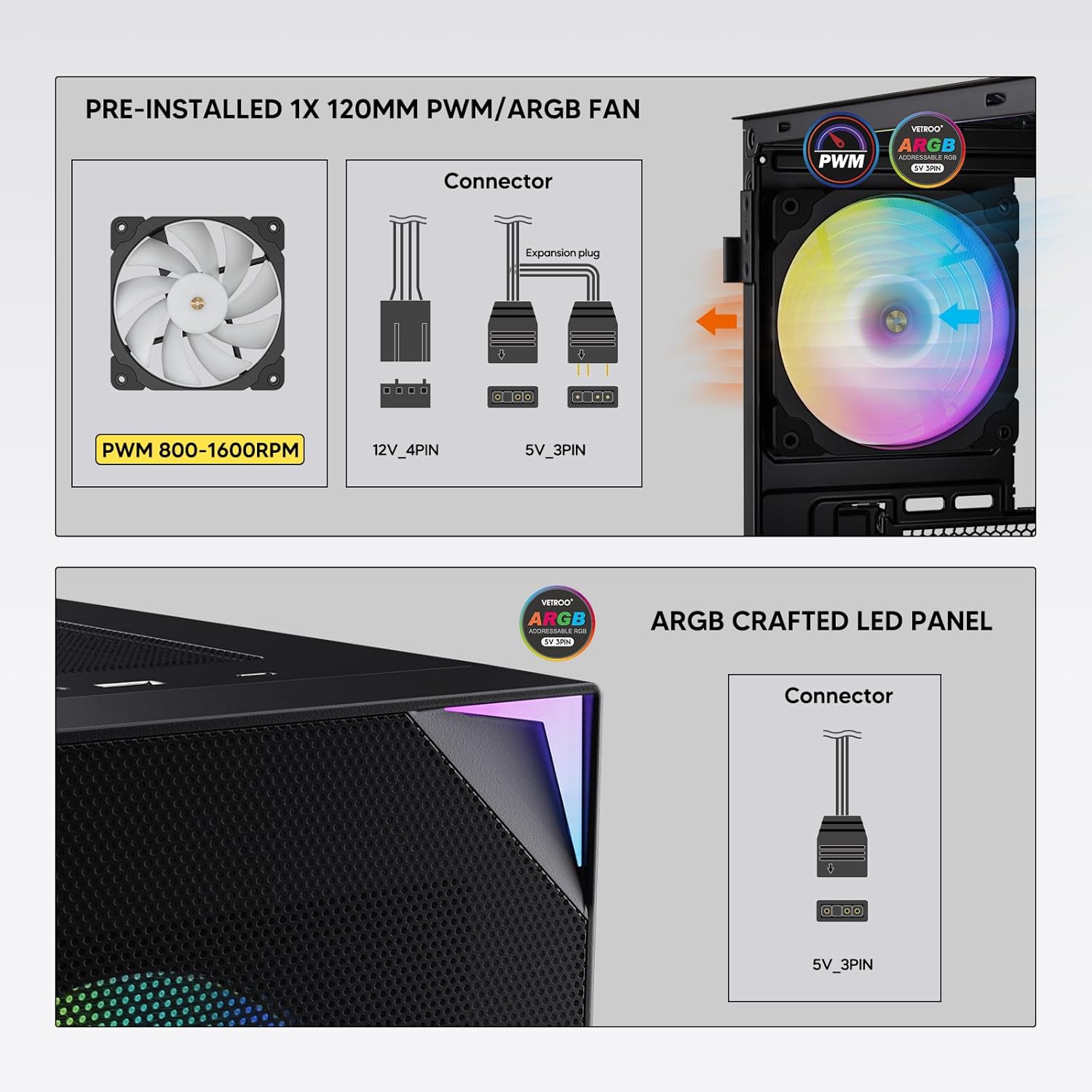
Figure 7: PWM and ARGB Connector Details
9. Gestión de cables
- Utilice los recortes de ruta de cables y los puntos de amarre detrás de la bandeja de la placa base para organizar los cables.
- The soft silicone grommets help protect cables and provide a clean look.
- La gestión adecuada de los cables mejora el flujo de aire y la estética.
Operación
1. Encendido inicial
- After all components are securely installed and cables connected, close the tempered glass side panel.
- Conecte el monitor, el teclado, el mouse y el cable de alimentación a la PC.
- Coloque el interruptor de encendido de su fuente de alimentación en la posición “ENCENDIDO”.
- Press the power button on the top I/O panel of the case to start your system.
2. Control de iluminación ARGB
- If connected to a compatible motherboard's 5V 3-pin ARGB header, the lighting of the pre-installed fan and LED strip can be controlled via your motherboard's RGB software (e.g., ASUS Aura Sync, MSI Mystic Light Sync, Gigabyte RGB Fusion, ASRock Polychrome Sync).
- Refer to your motherboard's manual for specific instructions on using its ARGB control software.
3 Gestión del flujo de aire
- The mesh front panel is designed for optimal air intake.
- Ensure that intake fans (typically front and bottom) and exhaust fans (typically rear and top) are configured to create positive or neutral air pressure for efficient cooling and dust prevention.

Figure 8: Airflow Diagram with Dust Filters
Mantenimiento
1. Limpieza del filtro de polvo
- The case is equipped with dust filters on the top and bottom panels.
- Regularly check and clean these filters to maintain optimal airflow and prevent dust buildup inside the system.
- Gently remove the magnetic dust filters and clean them with compressed air or by rinsing with water (ensure they are completely dry before re-installation).
2. Tempered Glass Panel Care
- Clean the tempered glass panel with a soft, lint-free cloth and a non-abrasive glass cleaner.
- Evite productos químicos agresivos o materiales abrasivos que puedan rayar o dañar el vidrio.
Solución de problemas
- El sistema no se enciende:
- Asegúrese de que el cable de alimentación esté conectado de forma segura tanto a la fuente de alimentación como a la toma de pared.
- Verifique que el interruptor de la fuente de alimentación esté en la posición “ENCENDIDO”.
- Check that the front panel power button cable is correctly connected to the motherboard header.
- Confirm all power cables (24-pin ATX, CPU, GPU) are properly seated in the motherboard and components.
- Los ventiladores no giran / El ARGB no se enciende:
- Check that the fan's PWM connector is securely plugged into a motherboard fan header.
- Verify the ARGB 3-pin connector is correctly attached to a 5V 3-pin ARGB header on the motherboard (not 12V RGB).
- Asegúrese de que el software ARGB de su placa base esté instalado y configurado correctamente.
- Los puertos USB no funcionan:
- Confirm the USB 3.0 and USB Type-C front panel cables are correctly connected to their respective motherboard headers.
- Check your motherboard manual for correct header locations.
- For other component-specific issues, refer to the instruction manuals for your motherboard, CPU, GPU, and other installed hardware.
Presupuesto
| Marca | Vetroo |
| Nombre del modelo | AL800 |
| Número de modelo del artículo | VT-CASE-AL800-BK (FBA) |
| Tipo de caso | Torre Media |
| Compatibilidad de la placa base | ATX, M-ATX, ITX |
| Color | Negro |
| Material | Metal, vidrio templado |
| Peso del artículo | 12.37 libras (aprox. 5.61 kg) |
| Dimensiones del producto (LxAnxAl) | 18.4 x 8.6 x 17.9 pulgadas (aprox. 46.7 x 21.8 x 45.5 cm) |
| Longitud máxima de GPU | 340 milímetros |
| Altura máxima del enfriador de CPU | 165 milímetros |
| Longitud máxima de la fuente de alimentación | 200 milímetros |
| Puertos de E / S frontales | 1x USB 3.2 Type-C, 2x USB 3.0, HD Audio (Mic/Headphone), Power, Reset |
| Apoyo de los fans | Front: 3x 120mm or 2x 140mm; Top: 2x 120mm or 2x 140mm; Rear: 1x 120mm; Bottom: 2x 120mm |
| Soporte del radiador | Front: 120/140/240/280/360mm; Top: 120/140/240mm; Rear: 120mm |
| Ventiladores preinstalados | 1x 120mm PWM/ARGB (Rear) |
Garantía y soporte
For warranty information, technical support, or to inquire about replacement parts, please visit the official Vetroo webSitio web o contacte directamente con el servicio de atención al cliente. Conserve su comprobante de compra para reclamaciones de garantía.
Official Vetroo Store: Vetroo Amazon Store
Ask a question about this manual
Ask about setup, troubleshooting, compatibility, parts, safety, or missing instructions. Manuals+ will review the question and use this page’s manual context to help answer it.