
1. Introducción
This manual provides essential information for the installation, operation, and maintenance of the Generic MS-S1561 Server Motherboard. This motherboard is designed to support Intel Xeon E5-2600 V3 and V4 series processors and DDR4 memory, utilizing the C612 chipset. Please read this manual thoroughly before proceeding with installation to ensure proper setup and functionality.

Figura 1: De arriba hacia abajo view of the Generic MS-S1561 Server Motherboard, showing CPU socket, RAM slots, and various connectors.
2. Configuración e instalación
Proper installation is crucial for the stable operation of your server system. Follow these steps carefully.
2.1 Compatibilidad de componentes
- Procesador: Intel Xeon E5-2600 V3/V4 series. Ensure the CPU socket type matches your processor.
- Memoria: DDR4 ECC/Non-ECC UDIMM/RDIMM. Refer to specifications for supported speeds and capacities.
- Conjunto de chips: Intel C612.
2.2 Instalación de la placa base
- Prepare el chasis: Ensure your server chassis is compatible with the motherboard form factor. Install standoffs in the chassis according to the motherboard's mounting holes.
- Instalar CPU: Carefully open the CPU socket lever. Align the processor with the socket, ensuring the triangular marks match. Gently place the CPU into the socket without force. Close the lever to secure the CPU.
- Instalar enfriador de CPU: Aplique pasta térmica (si no se aplicó previamente) e instale el disipador de CPU según las instrucciones del fabricante. Conecte el cable del ventilador de CPU al conector correspondiente en la placa base.
- Instalar memoria: Open the clips on the DDR4 memory slots. Align the memory modules with the key notch and press firmly until the clips snap into place. Refer to the motherboard's silkscreen for recommended slot population order for optimal performance.
- Monte la placa base: Carefully place the motherboard into the chassis, aligning the mounting holes with the standoffs. Secure the motherboard with screws.
- Conecte la electricidad: Connect the 24-pin ATX main power connector and the 8-pin (or 4-pin) CPU power connector from your power supply unit (PSU) to the motherboard.
- Conectar dispositivos de almacenamiento: Connect SATA data cables from your storage drives (HDDs/SSDs) to the SATA ports on the motherboard. Connect the corresponding power cables from the PSU to the drives.
- Conecte los cables del panel frontal: Connect the power switch, reset switch, HDD LED, power LED, and USB/audio headers from the chassis front panel to the corresponding pins on the motherboard. Refer to the motherboard's silkscreen or a detailed diagram for correct pin assignments.
- Instalar tarjetas de expansión: Insert any necessary PCIe expansion cards (e.g., graphics cards, network cards) into the appropriate PCIe slots and secure them with the chassis retention clips or screws.

Figure 2: Rear I/O panel of the Generic MS-S1561 Server Motherboard, showing various ports including USB, LAN, and VGA.
3. Instrucciones de funcionamiento
Una vez que todos los componentes estén instalados y conectados, puede encender su sistema.
3.1 Encendido
Ensure all power cables are securely connected. Press the power button on your chassis. The system should initiate the Power-On Self-Test (POST) process.
3.2 Acceso a BIOS/UEFI
During the POST sequence, press the designated key (commonly DEL, F2, o F10) to enter the BIOS/UEFI setup utility. Here you can configure boot order, system settings, and monitor hardware status.
3.3 Instalación del sistema operativo
Insert your operating system installation media (USB drive or DVD) and configure the boot order in the BIOS/UEFI to boot from the installation media. Follow the on-screen prompts to install your preferred operating system.
4. Mantenimiento
Regular maintenance helps ensure the longevity and stable performance of your motherboard and server system.
4.1 Eliminación de polvo
Periodically clean dust from the motherboard, CPU cooler, and chassis fans using compressed air. Ensure the system is powered off and unplugged before cleaning. Avoid using brushes or cloths that may generate static electricity.
4.2 Actualizaciones de BIOS/Firmware
Verifique el fabricante website (if available) for updated BIOS/firmware versions. Updates can improve compatibility, stability, and performance. Follow the specific instructions provided with the update utility carefully.
4.3 Comprobaciones de componentes
Occasionally inspect all cable connections (power, data, front panel) to ensure they are secure. Verify that all fans are spinning correctly and that there are no unusual noises or smells from the system.
5. Solución de problemas
Esta sección proporciona soluciones a problemas comunes que puede encontrar.
5.1 Sin alimentación/Sin POST (prueba automática de encendido)
- Compruebe las conexiones eléctricas: Ensure the 24-pin ATX and 8-pin CPU power cables are firmly connected to the motherboard and PSU. Verify the PSU is switched on and connected to a working power outlet.
- Reubicar los componentes: Power off and unplug the system. Reseat the CPU, RAM modules, and any expansion cards. Ensure they are properly seated in their respective slots.
- Borrar CMOS: Refer to the motherboard's manual or silkscreen for the CMOS clear jumper or button. Clearing CMOS can resolve boot issues caused by incorrect BIOS settings.
- Configuración mínima: Try booting with only the CPU, one RAM module, and the CPU cooler installed. If it boots, add components one by one to identify the faulty part.
5.2 Inestabilidad del sistema/fallos
- Comprobar temperaturas: Monitor CPU and system temperatures using BIOS or software utilities. Overheating can cause instability. Ensure CPU cooler is properly installed and fans are working.
- Prueba de memoria: Run a memory diagnostic tool (e.g., MemTest86) to check for faulty RAM modules.
- Actualizar controladores: Ensure all device drivers (chipset, LAN, etc.) are up to date for your operating system.
5.3 Periférico no detectado
- Comprobar conexiones: Verify that the peripheral (e.g., hard drive, USB device, expansion card) is correctly connected to the motherboard.
- Comprobar la configuración del BIOS: Ensure the relevant ports (SATA, USB, PCIe) are enabled in the BIOS/UEFI settings.
- Instalar controladores: Install the necessary drivers for the peripheral device.
6. Especificaciones
Key technical specifications for the Generic MS-S1561 Server Motherboard.
| Característica | Especificación |
|---|---|
| Número de modelo | MS-S1561 (Mfr Part Number: LlMER_GBFG__18568) |
| Dispositivos compatibles | Ordenador personal |
| Tecnología de memoria RAM | DDR4 |
| Ranuras de memoria disponibles | 2 |
| Tipo de conector S/PDIF | Óptico |
| Estándar de bus del sistema compatible | SATA 2 |
| ASIN | B0CSK62J8L |
| Fecha de primera disponibilidad | 17 de enero de 2024 |
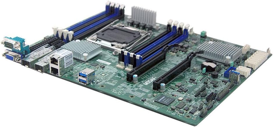
Figura 3: Angulado view of the Generic MS-S1561 Server Motherboard, highlighting various components and expansion slots.
7. Garantía y soporte
As a Generic branded product, warranty and support are typically handled by the seller or distributor from whom the product was purchased. Please refer to your purchase documentation or contact your vendor for specific warranty terms and technical support.
- Periodo de garantía: Varies by seller. Consult your purchase receipt or seller's policy.
- Apoyo técnico: Contact the seller (e.g., MinParts on Amazon) for assistance with product-specific issues.
- Recursos en línea: While specific manufacturer support for 'Generic' products may be limited, general troubleshooting guides for server motherboards and Intel C612 chipsets can be found online.