1. Introducción
This manual provides detailed instructions for the installation, operation, and maintenance of your EVURU 3-Phase Din Rail Automatic Transfer Switch (ATS). This device is designed to automatically switch between two power sources, typically a primary (utility) power and a secondary (generator or backup) power, ensuring uninterrupted power supply to critical loads. Please read this manual thoroughly before installation and operation to ensure safe and efficient use of the product.
2. Instrucciones de seguridad
- Sólo personal calificado: La instalación y el mantenimiento deben ser realizados por electricistas calificados de acuerdo con todos los códigos eléctricos locales y nacionales.
- Desconexión de energía: Always disconnect all power sources before installing, wiring, or servicing the ATS to prevent electric shock.
- Puesta a tierra adecuada: Ensure the ATS and all connected equipment are properly grounded.
- Volumentage y calificaciones actuales: Verify that the ATS voltage and current ratings match your application requirements. Exceeding ratings can cause damage or fire.
- Condiciones ambientales: Do not install the ATS in environments with excessive moisture, dust, corrosive gases, or extreme temperatures.
- Conexiones seguras: Ensure all electrical connections are tight and secure to prevent overheating and arcing.
3. Producto terminadoview
The EVURU 3-Phase Din Rail ATS is a compact and reliable solution for managing power transfer between two independent 3-phase power sources. It features a robust design suitable for industrial and commercial applications, ensuring seamless power continuity.
Características principales:
- Automatic and Manual Operation Modes.
- Din Rail Mountable for easy installation.
- Designed for 3-Phase, 4-Pole systems.
- Available in 63A, 100A, and 125A current ratings.
- Visual indicators for power source status.

Figura 3.1: Lado delantero view of the EVURU 3-Phase Din Rail Automatic Transfer Switch, showing input terminals for Source A and Source B, and the manual/auto selector switch.

Figura 3.2: Angular view of the ATS, highlighting the control panel with indicators and the manual operation handle.
4. Especificaciones
| Parámetro | Valor |
|---|---|
| Corriente de trabajo nominal | 63A, 100A, 125A (depending on model) |
| Vol. De trabajo nominaltage | 220V AC (3-Phase) |
| Volumen de aislamientotage | 690 V CA |
| Impact-Resistant Voltage | 8 kV |
| Tipo | 4P (4 polos) |
| Frecuencia | 50/60 Hz |
| Estándar | IEC / EN60947-6-1 |
| Montaje | Riel DIN de 35 mm |
| Material | Cobre (terminales) |
| Dimensiones (aprox.) | 1.18 x 0.79 x 0.39 inches (Package Dimensions, actual device dimensions may vary slightly) |
| Peso (aprox.) | 1.76 ounces (actual device weight may vary slightly) |
Nota: Las especificaciones están sujetas a cambios sin previo aviso. Consulte siempre la etiqueta del producto para obtener la información más precisa.
5. Configuración e instalación
Before proceeding with installation, ensure all power sources are disconnected and locked out. Follow all local and national electrical codes.
5.1 Din Rail Mounting
- Locate a suitable 35mm Din Rail within your electrical panel or enclosure.
- Align the ATS with the Din Rail. The device features integrated clips on the bottom for secure mounting.
- Press the ATS firmly onto the Din Rail until the clips engage and the device is securely fastened.

Figura 5.1: Abajo view of the ATS, illustrating the integrated clips for Din Rail mounting.
5.2 Instrucciones de cableado
Refer to the wiring diagram below for proper connection of power sources and load. Ensure all connections are made with appropriate wire gauges and are tightened to the specified torque.

Figura 5.2: Detailed wiring diagram for the ATS. Connect "Common power input" (Source A) and "Backup power input" (Source B) to their respective terminals. "Load output" connects to the downstream electrical panel. "Common control lines" and "Backup control line" are for automatic switching logic.
- Source A (Common Power Input): Connect the primary power source (e.g., utility grid) to the terminals labeled "Source A". Ensure correct phase (R, S, T) and neutral (N) connections.
- Source B (Backup Power Input): Connect the secondary power source (e.g., generator) to the terminals labeled "Source B". Ensure correct phase (R, S, T) and neutral (N) connections.
- Salida de carga: Connect the load (e.g., electrical panel for critical circuits) to the terminals labeled "Load Side".
- Cableado de control: Connect the control lines as indicated in the diagram. These lines are crucial for the automatic detection and switching logic.
- Toma de tierra: Ensure proper grounding for both power sources and the ATS unit.
After all connections are made, double-check wiring for correctness and tightness before restoring power.
6. Instrucciones de funcionamiento
The ATS offers both automatic and manual operation modes. The selection is made via the red rotary switch on the front panel.
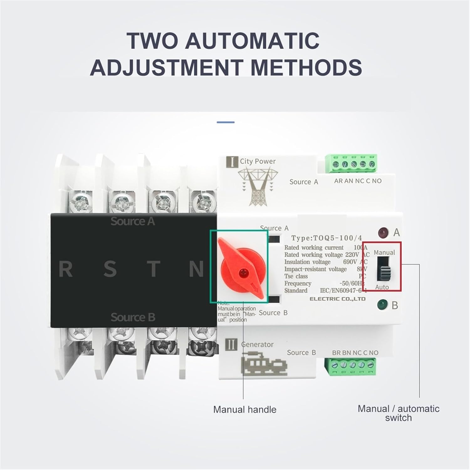
Figura 6.1: Detail of the manual handle and the manual/automatic selector switch on the ATS.
6.1 Automatic Mode (Auto)
In "Auto" mode, the ATS will automatically detect the presence and quality of power from Source A (primary) and Source B (backup) and switch the load accordingly.
- Set the rotary switch to the "Auto" position.
- When Source A is present and stable, the ATS will connect the load to Source A.
- If Source A fails or becomes unstable, the ATS will automatically transfer the load to Source B (if Source B is present and stable) after a pre-set delay.
- When Source A is restored and stable, the ATS will automatically transfer the load back to Source A after a pre-set delay.
Nota: The specific transfer delays are factory set or configurable depending on the model. Refer to the product label for details.
6.2 Manual Mode (Manual)
In "Manual" mode, the user can manually select the desired power source using the red handle.
- Set the rotary switch to the "Manual" position.
- To switch to Source A, rotate the red handle to the "A" position.
- To switch to Source B, rotate the red handle to the "B" position.
- To place the switch in a neutral or off position (disconnecting both sources), rotate the handle to the center position.
Precaución: When operating in manual mode, ensure that the selected power source is stable and safe to connect to the load. Avoid switching under heavy load conditions if possible.
7. Mantenimiento
Regular maintenance ensures the longevity and reliable operation of your ATS. Always disconnect power before performing any maintenance.
- Inspección periódica: Annually inspect the ATS for any signs of physical damage, discoloration, or loose connections.
- Estanqueidad del terminal: Revise y vuelva a apretar periódicamente todos los tornillos de los terminales para garantizar un buen contacto eléctrico.
- Limpieza: Keep the ATS free from dust and debris. Use a dry, soft cloth for cleaning. Do not use liquid cleaners or solvents.
- Prueba funcional: Periodically test the automatic transfer function by simulating a primary power failure (if safe to do so and with proper precautions).
8. Solución de problemas
Si tiene problemas con su ATS, consulte los siguientes problemas y soluciones comunes:
| Problema | Posible causa | Solución |
|---|---|---|
| ATS does not transfer automatically. |
|
|
| Load remains off after transfer. |
|
|
| ATS makes clicking noises but doesn't switch. |
|
|
Si el problema persiste después de intentar estas soluciones, comuníquese con un electricista calificado o con el soporte del fabricante.
9. Garantía y soporte
EVURU products are manufactured to high-quality standards and are backed by a limited warranty against defects in materials and workmanship. For specific warranty terms and conditions, please refer to the warranty card included with your product or visit the official EVURU websitio.
For technical support, troubleshooting assistance, or warranty claims, please contact EVURU customer service through the contact information provided on our website or your purchase documentation. Please have your product model and purchase date available when contacting support.
Websitio: www.evuru.com (Nota: Este es un marcador de posición URL, consulte la documentación del producto real para obtener información correcta websitio.)