
1. Introducción
The Owon SDS210 is a high-performance 100 MHz, 2-channel digital oscilloscope designed for accurate signal analysis. With a real-time sampling rate of 1 GS/s and a 20M record length, it provides comprehensive waveform capture and analysis capabilities. This manual provides essential information for setting up, operating, and maintaining your SDS210 oscilloscope.
- Ancho de banda de 100 MHz: Capable of analyzing signals up to 100 MHz.
- 2 canales: Allows simultaneous analysis of two signals.
- 1 GS/s Real-time SampTasa de ling: Ensures detailed capture of transient events.
- 20M Record Length: Provides extensive waveform storage for in-depth analysis.
- Pantalla LCD TFT de 7 pulgadas: Clear visualization of waveforms and measurement data.
- 30 Automatic Measurements: For quick and precise waveform parameter analysis.
- Análisis del espectro FFT: Advanced signal analysis in the frequency domain.
- Conectividad USB: Supports USB Host and USB Device interfaces for data transfer and PC control.
2. Información de seguridad
Lea y comprenda todas las instrucciones de seguridad antes de utilizar el dispositivo. El incumplimiento de estas instrucciones podría provocar lesiones o daños al instrumento.
- Utilice únicamente el adaptador de corriente suministrado con el instrumento.
- No opere el osciloscopio en ambientes húmedos o secos.amp condiciones.
- Asegúrese de que haya una ventilación adecuada para evitar el sobrecalentamiento.
- No intente reparar ni modificar el instrumento usted mismo. Encargue cualquier servicio técnico a personal cualificado.
- Always connect the probe ground lead to earth ground before connecting the probe tip to the circuit under test.
- Observar todos los vol.tage ratings and input limits specified for the oscilloscope and probes.
3. Producto terminadoview
3.1 Panel frontal
The front panel features the main display, control buttons, and input connectors.

Figure 3.1: Front and Rear Panel Layout with Key Components. This image shows the Power Switch, Function Keys, Button and Knob Control Area, Oscilloscope Signal Input Ports (CH1, CH2), Probe Compensation Output, USB Host Interface, Foldable Handle, Ventilation Holes, Power Socket, and USB Device Interface.
- Interruptor de alimentación: Turns the oscilloscope on or off.
- Teclas de función: Access various menus and settings.
- Área de control de botones y perillas: Includes controls for vertical, horizontal, trigger, and menu navigation.
- Oscilloscope Signal Input Port (CH1, CH2): BNC connectors for connecting probes to input signals.
- Salida de compensación de la sonda: 5V/1kHz signal output for probe calibration.
- Interfaz de host USB: Para conectar dispositivos de almacenamiento USB para guardar o recuperar datos.
3.2 Panel trasero
The rear panel includes the power input and additional connectivity options.
- Mango plegable: Para una fácil portabilidad.
- Orificios de ventilación: Esencial para la disipación del calor.
- Toma de corriente: Se conecta a la fuente de alimentación de CA.
- Interfaz del dispositivo USB: Se utiliza para conectar el osciloscopio a una PC para transmisión de datos y control remoto.
4. Configuración
4.1 Desembalaje
Carefully remove the oscilloscope and all accessories from the packaging. Verify that all components listed in the packing list are present and undamaged. Keep the original packaging for future transport or storage.
4.2 Conexión de alimentación
- Conecte el cable de alimentación provisto a la toma de corriente en el panel trasero del osciloscopio.
- Conecte el otro extremo del cable de alimentación a una toma de corriente CA con conexión a tierra.
4.3 Conexión de sonda
Connect the oscilloscope probes to the CH1 and CH2 BNC input ports on the front panel. Ensure the connectors are securely twisted into place.
4.4 Compensación de sonda
Before taking measurements, it is crucial to compensate your probes to ensure accurate readings. This process matches the probe's capacitance to the oscilloscope's input capacitance.
- Set the probe attenuation to 10X.
- Connect the probe tip to the Probe Compensation Output terminal (5V/1kHz) on the front panel.
- Connect the probe's ground clip to the ground terminal next to the compensation output.
- Press the AUTO button to automatically adjust the waveform.
- Observe the square wave displayed on the screen. Adjust the trimmer capacitor on the probe until the square wave corners are flat, without overshoot or undershoot.
4.5 PC Connection (USB Device Interface)
To connect the oscilloscope to a computer for remote control or data transfer:
- Use a standard USB cable to connect the USB Device Interface port on the rear panel of the oscilloscope to a USB port on your computer.
- Install the necessary drivers and software provided by OWON for your specific operating system.
5. Funcionamiento básico
5.1 Encendido / Apagado
Press the Power Switch on the front panel to turn the oscilloscope on. Press it again to turn it off.
5.2 Visualización sobreview
The SDS210 features a 7-inch TFT LCD display that provides a clear view of waveforms, measurement results, and instrument settings.
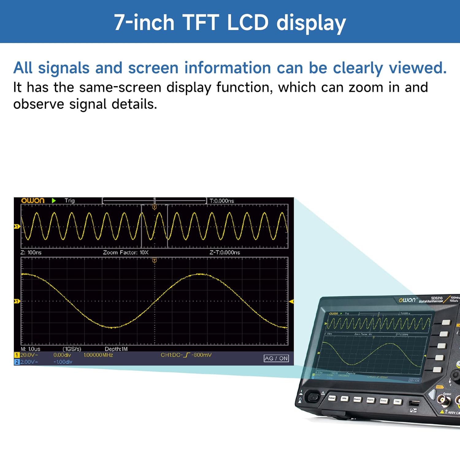
Figure 5.2: 7-inch TFT LCD Display. All signals and screen information can be clearly viewed. It has a same-screen display function, which can zoom in and observe signal details.
5.3 Visualización básica de forma de onda
After connecting a signal to an input channel, press the AUTO button. The oscilloscope will automatically adjust the vertical, horizontal, and trigger settings to display a stable waveform.
5.4 controles verticales
The vertical controls adjust the amplitude and position of the waveform.
- Vertical Position Knob: Moves the waveform up or down on the screen.
- Vertical Scale Knob (V/div): Adjusts the vertical sensitivity (volts per division).
- Botones CH1/CH2: Selects the active channel for adjustments or turns channels on/off.
5.5 controles horizontales
The horizontal controls adjust the time base and position of the waveform.
- Horizontal Position Knob: Moves the waveform left or right on the screen.
- Horizontal Scale Knob (s/div): Adjusts the time base (seconds per division).
5.6 controles de disparo
The trigger controls stabilize repetitive waveforms and capture single-shot events.
- Trigger Level Knob: Establece el voltage level at which the trigger occurs.
- Trigger Menu Button: Accesses trigger settings such as edge, pulse, video, and slope.
- Force Button: Forces a trigger event.
6. Funciones avanzadas
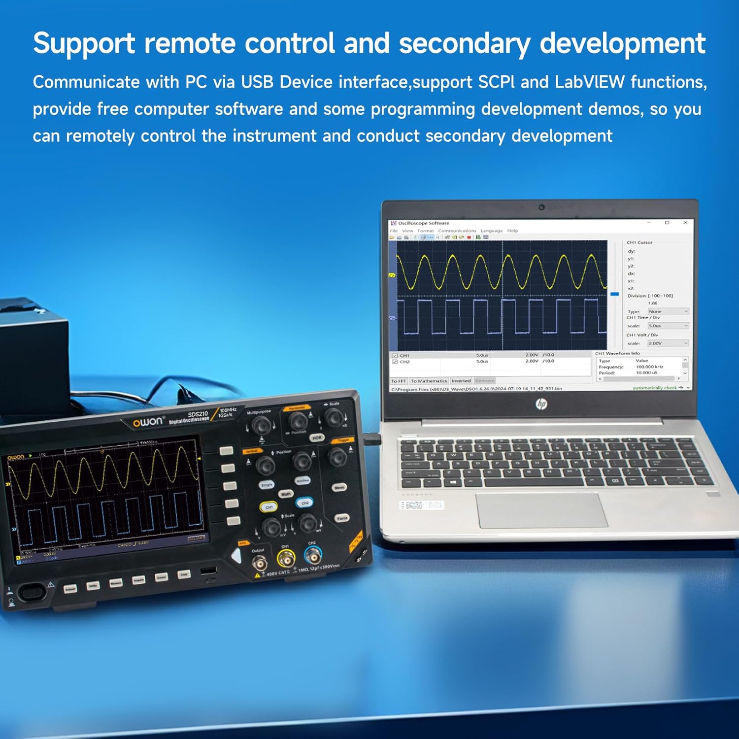
Figure 6.0: Advanced Measurement and Analysis Modes. This image illustrates the 6-digit High-precision Frequency counter, FFT Spectrum Analysis, Cursor Measurements, 30 Automatic Waveform Measurements, Save/Recall functions, and X-Y mode.
6.1 Mediciones automáticas
The SDS210 offers 30 types of automatic waveform measurements for quick and accurate analysis of signal parameters. Press the MEASURE button to access the automatic measurement menu.
- Common measurements include Period, Frequency, Mean, Peak-PK, RMS, Max, Min, Top, Base, Amplitude, Overshoot, Preshoot, Rise Time, Fall Time, Pulse Width, Delay, Duty Cycle, and more.
6.2 Análisis del espectro FFT
Perform Fast Fourier Transform (FFT) to analyze signals in the frequency domain. This is useful for identifying harmonics, distortion, and noise components.
- Press the MATH button.
- Select 'FFT' from the Math menu.
- Adjust the FFT settings such as source, window type, and display format.
6.3 Cursor Measurements
Use cursors to manually measure specific points on a waveform. Press the CURSOR button to activate and control the cursors.
- Volumentage Cursors: Medir voltage differences (ΔV).
- Time Cursors: Measure time differences (ΔT).
6.4 Save/Recall Waveforms
The oscilloscope allows you to save and recall waveform data and instrument settings to internal memory or a connected USB drive.
- Press the SAVE button to access saving options.
- Select the desired save type (waveform, setup, image) and destination (internal, USB).
6.5 X-Y Mode
X-Y mode is used to display the relationship between two signals, often for phase comparison or Lissajous figures.
- Ensure signals are connected to CH1 and CH2.
- Access the Display menu and select X-Y mode.
6.6 Control remoto y software
The SDS210 supports remote control and secondary development via its USB Device Interface, utilizing SCPI (Standard Commands for Programmable Instruments) and LabVIEW functions. Free computer software and programming development demos are available to facilitate remote instrument control.

Figure 6.6: Remote Control and Secondary Development. Communicate with a PC via the USB Device interface, supporting SCPI and LabVIEW functions. Free computer software and programming development demos are provided for remote control and secondary development.
7. Mantenimiento
7.1 Limpieza
Para limpiar el instrumento, utilice un paño suave.ampened with a mild detergent. Do not use abrasive cleaners or solvents that could damage the casing or display. Ensure the instrument is powered off and disconnected from the power source before cleaning.
7.2 Almacenamiento
When not in use for extended periods, store the oscilloscope in a dry, dust-free environment. Use the original packaging for protection during storage or transport.
7.3 Ventilación
The oscilloscope is equipped with ventilation holes on the rear panel to prevent overheating. Ensure these holes are not obstructed during operation to allow for proper airflow.
8. Solución de problemas
Esta sección proporciona soluciones a problemas comunes que puede encontrar.
- Sin energía: Check the power cord connection and the power outlet. Ensure the power switch is in the 'ON' position.
- Sin visualización de forma de onda: Verify that a signal is connected to the input channel. Check probe connections and ensure the channel is enabled. Press the AUTO button to automatically adjust settings.
- Forma de onda inestable: Adjust the trigger level and trigger settings (e.g., edge, slope). Ensure the trigger source is correctly selected.
- Medidas inexactas: Perform probe compensation as described in Section 4.4. Check the probe attenuation setting on both the probe and the oscilloscope.
- Problemas de conexión USB: Ensure the correct drivers are installed on your PC. Try a different USB cable or port.
If the problem persists, contact OWON customer support or your local distributor for assistance.
9. Especificaciones
The following table details the technical specifications for the Owon SDS210 Digital Oscilloscope.

Figure 9.0: Owon SDS210 Series Oscilloscope Specifications. This table provides detailed specifications including Bandwidth, Sample Rate, Acquisition Mode, Input Coupling, Input Impedance, Probe Attenuation Factor, Record Length, Horizontal Scale, Vertical Sensitivity, Automatic Measurement types, Waveform Math functions, Waveform Storage, Lissajous Figures, Trigger Type, Communication Interface, Frequency Counter, and Waveform Generator Specifications (for SDS210S, SDS215S, SDS220S models).
| Característica | Specification (SDS210) |
|---|---|
| Fabricante | OWON |
| Número de modelo | SDS210-OW |
| Ancho de banda | 100 MHz |
| Canales | 2 canales |
| Samptasa | 1 GS/s |
| Duración del registro | 20 millones |
| Modo de adquisición | Normal, Peak detect, Averaging |
| Acoplamiento de entrada | CC, CA, Tierra |
| Impedancia de entrada | 1MΩ±2%, in parallel with 20 pF±5 pF |
| Factor de atenuación de la sonda | 1X, 10X, 100X, 1000X |
| Escala horizontal (s/div) | 2 ns/div-1000 s/div, step by 1-2-5 |
| Sensibilidad vertical | 2 mV/div - 10 V/div |
| Medida Automática | Periodo, Frecuencia, Media, PK-PK, RMS, Máx., Mín., Superior, Base, Amplitude, Overshoot, Preshoot, Rise Time, Fall Time, +PulseWidth, -PulseWidth, +Duty Cycle, -Duty Cycle, Delay A→B↑, Delay A→B↓, Cycle RMS, Cursor RMS, Screen Duty, Phase, +PulseCount, -PulseCount, RiseEdgeCnt, FallEdgeCnt, Area, and Cycle Area. |
| Matemáticas de forma de onda | +, -, ×, ÷, FFT |
| Almacenamiento de formas de onda | 16 waveforms |
| Lissajous's Bandwidth | full bandwidth |
| Lissajous's Figure Phase Difference | ±3 grados |
| Tipo de disparador | Edge, Vídeo |
| Interfaz de comunicación | Host y dispositivo USB |
| Contador de frecuencia | disponible |
| Dimensiones del producto (L x An x Al) | 29.97 x 7.01 x 15.24 cm (11.8 x 2.76 x 6 pulgadas) |
| Peso del producto | 1.1 kilogramos (38.8 onzas) |
10. Garantía y soporte
10.1 Información de garantía
For detailed warranty information, please refer to the warranty card included with your product or contact your authorized OWON dealer or the manufacturer directly. Warranty terms and conditions may vary by region and retailer.
10.2 Atención al cliente
If you require technical assistance, have questions about your product, or need to report an issue, please contact OWON customer support. Contact information can typically be found on the manufacturer's official websitio o a través de la documentación de su producto.