
1. Introducción
This manual provides detailed instructions for the safe and efficient use of the GODIYMODULES DC-DC 400W High-Power Step Down Buck Converter, Model SZ6012-001. This module is designed to convert a higher DC input voltage to a lower, adjustable DC output voltage with constant current capabilities. Please read this manual thoroughly before installation and operation.
2. Información de seguridad
- Seguridad eléctrica: Always ensure power is disconnected before making any connections or adjustments to prevent electric shock or damage to the module.
- Polaridad: It is strictly forbidden to connect the positive and negative poles of the input and output in reverse. Reversed input will burn the fuse, and reversed output will damage the control board.
- sobrevoltajetagy Protección: The module has input undervoltage protection (shuts off below 10.5V), but it does no have input overvoltagProtección electrónica. Asegúrese de que el volumen de entradatagy no supere los 60V.
- Disipación de calor: For continuous high-power operation (above 280W or 12A), forced cooling (e.g., a fan) is required to prevent overheating.
- Cargas inductivas: When charging batteries or connecting inductive loads (e.g., motors), an anti-reverse diode must be added to the output to prevent damage.
- Ambiente: Operate the module within the specified temperature range of -10°C to +85°C.
3. Producto terminadoview
3.1. Características principales
- Salida de alta potencia: Natural heat dissipation supports up to 280W/12A. With forced cooling, it can achieve up to 400W.
- Volumen de entrada ampliotage: Accepts 10.5V to 60V DC input.
- Salida ajustable: Vol de salidatage range from 0V to 45V (must meet step-down conditions, output is approximately 80% of input maximum).
- Corriente constante: Adjustable constant current output from 0.2A to 15A.
- Alta eficiencia: Up to 97% conversion efficiency, especially when output voltage está por encima de 10 V.
- Características de protección: Includes input undervoltage protection and constant current short circuit protection.
- Indicadores: Features a constant current indicator (red LED) and a work indicator (blue LED).
- Conexión fácil: Equipped with welding-free 25A terminal blocks.
3.2. Identificación de componentes
The following image illustrates the key components and connection points of the buck converter module:
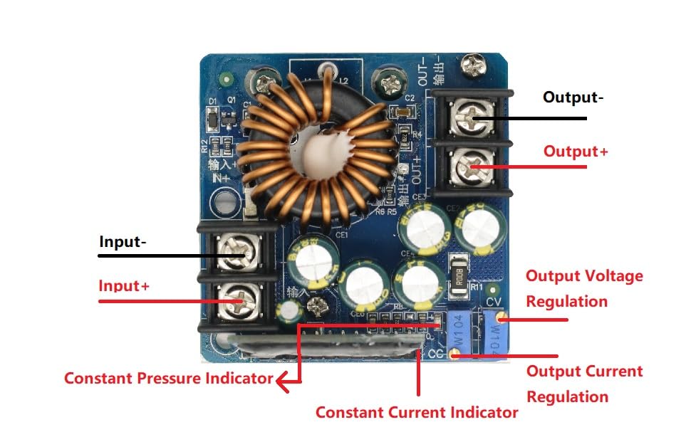
Figura 1: Labeled diagram of the GODIYMODULES DC-DC 400W High-Power Step Down Buck Converter. This image highlights the Input+ (IN+), Input- (IN-), Output+ (OUT+), Output- (OUT-), Output Voltage Regulation potentiometer (CV), Output Current Regulation potentiometer (CC), Constant Pressure Indicator, and Constant Current Indicator.
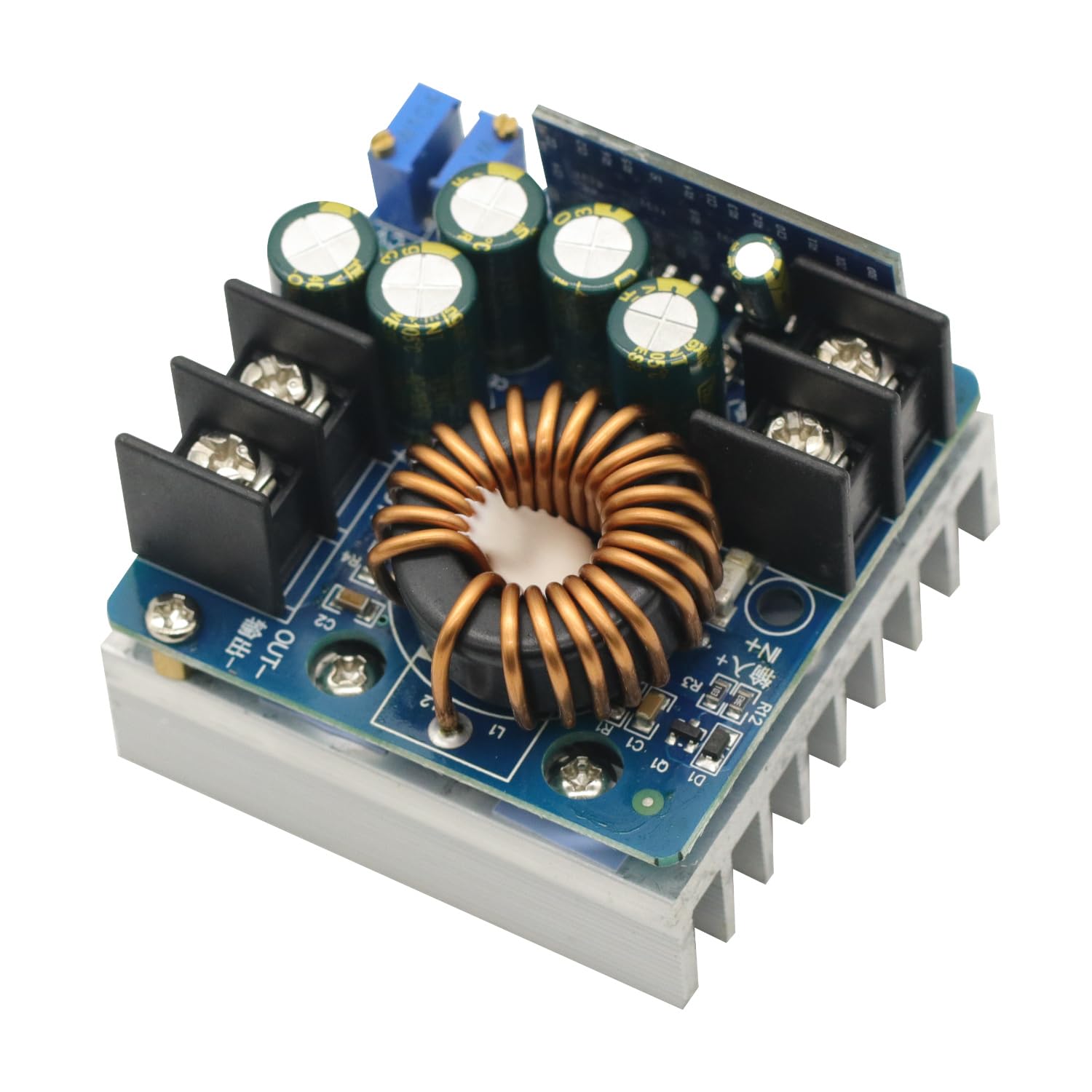
Figura 2: De arriba hacia abajo view of the GODIYMODULES DC-DC 400W High-Power Step Down Buck Converter, showcasing the inductor, capacitors, and heatsink.
4. Especificaciones
| Parámetro | Valor |
|---|---|
| Nombre del módulo | 400W Step-Down Constant Voltage y corriente constante |
| Module Nature | Non-isolated step-down module (BUCK) |
| Vol de entradatage | 10.5 V - 60 V CC |
| Vol de salidatage Rango | 0V - 45V (adjustable, max output approx. 80% of input) |
| Volumen mínimo de salidatage | 0V (+1V) |
| Output Constant Current | 0.2A - 15A (continuously adjustable) |
| Potencia máxima de salida | 400W (with forced cooling) |
| Continuous Max Working Power | 280W (under ventilated environment) |
| Continuous Max Working Current | 12A (under ventilated environment) |
| Subvol. de entradatage Protección | Yes (output turns off below 10.5V, approx. 0.5V error) |
| Sobrevoltaje de entradatage Protección | No (overvoltage is prohibited) |
| Temperatura de trabajo | -10°C to +85°C (enhance heat dissipation above 65°C) |
| Frecuencia de trabajo | 100 kHz |
| Eficiencia de conversión | Up to 97% (depends on input/output, current, and voltage diferencia) |
| Protección contra cortocircuitos | Yes (constant current protection) |
| Protección de conexión inversa de entrada | Yes (but short-circuiting input with reverse connection will burn the fuse) |
| Output Anti-Recharge | No (requires external anti-reverse diode for battery charging/inductive loads) |
| Indicador de trabajo | Yes (blue LED) |
| Indicador de corriente constante | Yes (red LED, lights up when constant current is active) |
| Método de conexión | Welding-free 25A terminal block |
| Dimensiones del módulo | 60 mm (largo) x 60 mm (ancho) x 45 mm (alto) |
| Peso neto | 170 gramos |
5. Configuración
5.1. Conexiones de cableado
Refer to Figure 1 for component identification. Use appropriate gauge wires for your expected current draw.
- Conexión de entrada: Connect your DC power source to the EN+ (entrada positiva) y EN- (negative input) terminals. Ensure correct polarity.
- Conexión de salida: Connect your load or device to the FUERA+ (salida positiva) y AFUERA- (negative output) terminals. Ensure correct polarity.
- Battery Charging/Inductive Loads: If charging a battery or connecting an inductive load (e.g., a motor), an external anti-reverse diode must be connected in series with the output to prevent current backflow into the module.
5.2. Encendido inicial
Before applying power, double-check all connections for correct polarity and secure fastening. Once verified, apply power to the input terminals. The blue work indicator LED should illuminate.
6. Instrucciones de funcionamiento
6.1. Ajuste del volumen de salidatagmi (CV)
- Connect the input power source.
- Without a load connected, or with a light load, use a multimeter to monitor the output voltage.
- Girar el Vol de salidatagReglamento electrónico (CV) potentiometer (refer to Figure 1) clockwise to increase the output voltagGire en sentido horario o antihorario para disminuirlo. Ajuste al volumen deseado.tage.
6.2. Adjusting Output Current (CC)
The constant current feature is primarily used for charging batteries or driving LEDs.
- First, set the desired output voltage as described above.
- To set the constant current limit, you can either:
- Connect a suitable ammeter in series with the output and a load.
- Alternatively, for battery charging, connect a discharged battery.
- Girar el Output Current Regulation (CC) potentiometer (refer to Figure 1) clockwise to increase the current limit or counter-clockwise to decrease it. Adjust to your desired current limit.
- When the module operates in constant current mode (e.g., when the load draws more current than the set limit, or during battery charging), the red Indicador de corriente constante LED will illuminate. If the output current is below the set limit, the module operates in constant voltage mode, and the red LED will be off.
6.3. Vídeo de demostración
This video demonstrates the adjustment of output voltage and current, and the module's performance under load.
Vídeo 1: Demonstration of the GODIYMODULES DC-DC 400W Step Down Buck Converter. The video shows the process of adjusting the output voltage and current using the potentiometers, and monitoring the values on external measurement equipment. It illustrates the module's ability to maintain a stable output under varying load conditions.
7. Mantenimiento
- Limpieza: Mantenga el módulo limpio y libre de polvo y residuos. Utilice un paño suave y seco para limpiarlo.
- Disipación de calor: Regularly check that the heatsink is clear of obstructions. If operating at high power, ensure any additional cooling fans are functioning correctly.
- Conexiones: Inspeccione periódicamente todas las conexiones del cableado para asegurarse de que estén seguras y libres de corrosión.
- Condiciones ambientales: Avoid exposing the module to excessive moisture, extreme temperatures, or corrosive environments.
8. Solución de problemas
- Sin volumen de salidatage:
- Verifique la fuente de alimentación de entrada.
- Verificar volumen de entradatage is above 10.5V (undervoltage protection will shut off output below this).
- Ensure input and output polarities are correct. Reversed input will burn the fuse.
- Compruebe si el volumen de salidatage potentiometer (CV) is adjusted to 0V.
- Sobrecalentamiento del módulo:
- Reduce the output power or current.
- Asegúrese de que haya una ventilación adecuada alrededor del módulo.
- For continuous operation above 280W or 12A, install a cooling fan.
- Constant Current Indicator (Red LED) Not Lighting Up:
- This is normal if the load is drawing less current than the set constant current limit (module is in constant voltagmodo electrónico).
- If you expect constant current operation, ensure the load is sufficient to draw current above the set limit, or that the battery being charged is sufficiently discharged.
- Damage from Reverse Polarity:
- Input reverse connection will burn the input fuse. Replace the fuse if accessible and verify polarity before reapplying power.
- Output reverse connection will damage the control board, which is generally not repairable and requires module replacement.
9. Garantía y soporte
For technical support or warranty inquiries regarding your GODIYMODULES DC-DC 400W High-Power Step Down Buck Converter (Model SZ6012-001), please contact the seller or manufacturer through the platform where the product was purchased. Please have your purchase details and model number available when contacting support.