
Introducción
This manual provides essential information for the proper setup, operation, and maintenance of your GODIYMODULES 1969 Class A Power Amplifier Board. Please read these instructions carefully before installation and use to ensure optimal performance and longevity of the product.
Producto terminadoview
The GODIYMODULES 1969 Class A Power Amplifier Board is a high-fidelity audio amplifier designed for enthusiasts. It features a robust 2N3055 power amplifier tube and delivers 10-15W of output sound power. This product is supplied as a pair of assembled PCB boards, ready for integration into your audio system.
- Fuerza Amplifier Tube: 2N3055
- Vol de trabajotage: DC 12V-35V (requires a 9-26V transformer with power greater than 100W)
- Output Sound Power: 10-15 W
- Dimensiones del tablero: 100mm x 78mm x 36mm (Angle aluminum with 2 fixed holes, 53mm apart)
- Default Current Setting: 24V, 1.2A (Higher current increases heat output)
- Oradores recomendados: 3-5 inch full-range speakers, or 5-8 inch diameter full-range speakers. Speakers with power below 120 watts and below 8 inches are suitable.
- Componentes incluidos: 2 PCS (1 Pair) 1969 Class A Power Amptableros lificadores

Figura 1: Angulado view of a single 1969 Class A Power AmpTablero de visualización, muestraasing components and heatsink.

Figura 2: De arriba hacia abajo view de dos amplifier boards, highlighting the layout of components and terminals.
Presupuesto
| Fabricante | MÓDULOS DE GODIY |
| Número de modelo | 1969 Class A Power Amptablero más duradero |
| Volumen máximo de suministrotage | 35 voltios (CC) |
| Tipo de montaje | Montaje de orificio pasante |
| Número de canales | 2 |
| Potencia de salida | 15 vatios |
| Componentes incluidos | 2pcs (1 Pair) |
Configuración
Careful attention to wiring and power supply is crucial for the safe and effective operation of the amptableros de filtro.
Requisitos de suministro de energía
- El amplifier boards require a DC working voltagy entre 12 V y 35 V.
- An appropriate transformer (9-26V AC output) with a power rating greater than 100W is necessary for the rectifier board.
Conexión de altavoces
- Connect 3-5 inch full-range speakers for optimal performance.
- Alternatively, speakers with a diameter of 5-8 inches and a power rating below 120 watts are also suitable.
Diagrama de cableado
Refer to the following diagram for proper connection of the amplifier boards to the power supply, rectifier, and speakers.
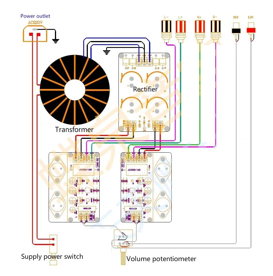
Figure 3: Detailed wiring diagram showing connections from AC power outlet to transformer, rectifier, amplifier boards, and output to speakers and volume potentiometer.
Instrucciones de funcionamiento
Ajuste actual
It is recommended to adjust the quiescent current for optimal Class A operation. The default setting is 1.2A at 24V.
- Set a universal multimeter to measure current (10-20A range).
- Disconnect the VCC line del poder amptablero más duradero.
- Connect the red probe of the multimeter to the VCC terminal of the rectifier board.
- Connect the black probe of the multimeter to the VCC terminal of the power amplifier board. This completes the circuit through the multimeter, allowing current measurement.
- Adjust the potentiometer labeled KT2 (W202) on the board to achieve the desired current. A setting of 1.2A is recommended.
- Nota importante: The measurement points for current and midpoint voltage are different. Ensure you change the red probe's connection point when switching between current and midpoint voltagy mediciones.

Figura 4: Primer plano de la amplifier board, indicating the location of adjustable components like KT2 (W202) for current adjustment.
Mantenimiento
To ensure the longevity and stable performance of your amplifier boards, consider the following maintenance guidelines:
- Ventilación: Asegúrese de que haya un flujo de aire adecuado alrededor del amplifier boards, especially given that Class A amplifiers generate significant heat. Do not obstruct the heatsinks.
- Limpieza: Periodically inspect the boards for dust accumulation. Use a soft brush or compressed air to gently remove dust from components and heatsinks.
- Conexiones: Regularly check all wiring connections to ensure they are secure and free from corrosion. Loose connections can lead to intermittent performance or damage.
- Condiciones ambientales: Operar el amplifier in a dry environment, away from excessive humidity, direct sunlight, and extreme temperatures.
Solución de problemas
Si tiene problemas con su amplifier boards, review Los siguientes problemas comunes y soluciones:
- Sin salida de sonido:
- Verify all power connections are secure and the power supply is providing the correct voltage.
- Verifique las conexiones de los altavoces para comprobar que la polaridad sea la adecuada y el contacto sea seguro.
- Ensure the audio input source is functioning correctly.
- Sonido distorsionado:
- Check the input signal level; excessive input can cause distortion.
- Asegúrese de que los altavoces coincidan correctamente con el amplifier's output power and impedance.
- Verify the current adjustment (KT2/W202) is set correctly (e.g., 1.2A).
- Calor excesivo:
- Clase A amplifiers naturally run hot. However, ensure adequate ventilation and heatsink clearance.
- Check the quiescent current setting; a higher current will generate more heat.
- High Frequency Ringing (>12kHz):
- Some users have reported that adding a 500pF capacitor in parallel with resistor R5 can help mitigate high-frequency ringing. This modification should only be performed by experienced individuals.
Información de garantía
Specific warranty details for this product are typically provided at the point of purchase or by the seller. Please refer to your purchase documentation or contact your retailer for information regarding warranty coverage and terms.
Apoyo
For technical assistance, troubleshooting beyond this manual, or inquiries regarding your GODIYMODULES 1969 Class A Power Amplifier Board, please contact the seller or manufacturer directly through the platform where the product was purchased. Provide your order details and a clear description of the issue for efficient support.