
1. Introducción
This manual provides detailed instructions for the setup, operation, and maintenance of the GODIYMODULES AD9851 DDS Signal Generator Module. This module is designed for generating precise sine and square waveforms, suitable for various electronic projects and testing applications.
2. Producto terminadoview
The AD9851 DDS Signal Generator Module is a compact and versatile device capable of producing high-frequency sine waves up to 70MHz and square waves up to 1MHz. It features both parallel and serial data input options, selectable via a jumper, offering flexibility for integration into different systems. The module incorporates the AD9851 chip, known for its direct digital synthesis capabilities and a clock frequency up to 180MHz.

Figura 2.1: Arriba view of the AD9851 DDS Signal Generator Module, showing the main chip and components.
3. Configuración y conexiones
Proper connection of the module is crucial for its functionality. Refer to the pinout diagram below for detailed connection points.
3.1 Fuente de alimentación
- CCV: Connect to your positive power supply (e.g., +5V).
- TIERRA: Connect to the ground of your power supply.
- Ensure the power supply is stable and within the module's specified voltage rango.
3.2 Entrada de datos
The module supports both parallel and serial data input. A jumper on the board allows selection between these modes.
- Parallel Data Pins (D0-D7): Used for parallel communication with a microcontroller.
- Serial Data Pins (W_CLK, FU_UD, DATA): Se utiliza para comunicación en serie.
- REINICIAR: Reset pin for the AD9851 chip.
3.3 Waveform Outputs
- QOUT1, QOUT2: Square wave outputs.
- ZOUT1, ZOUT2: Sine wave outputs.
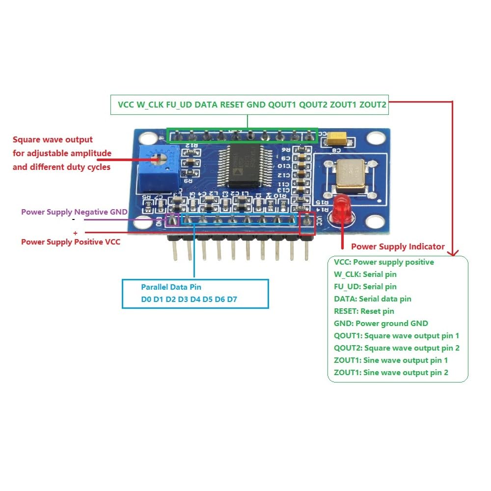
Figure 3.1: Pinout diagram of the AD9851 module with descriptions for power, data, and output pins.
4. Instrucciones de funcionamiento
The AD9851 module generates waveforms based on digital input signals. Programming the AD9851 chip is typically done via a microcontroller (e.g., Arduino, ESP32) using either parallel or serial communication protocols.
4.1 Sine Wave Generation
- The module can generate sine waves from 0Hz up to 70MHz.
- Frequency is controlled by sending appropriate frequency tuning words to the AD9851 chip via the selected data input method.
- The output sine waves are available on the ZOUT1 and ZOUT2 pins.
4.2 Square Wave Generation
- Square waves can be generated from 0Hz up to 1MHz.
- The square wave outputs are available on the QOUT1 and QOUT2 pins.
- An onboard potentiometer allows for adjustment of the square wave's ampligereza y ciclo de trabajo.
4.3 Data Input Selection
A jumper on the module allows you to select between parallel and serial data input modes. Ensure the correct mode is selected to match your microcontroller's communication method.
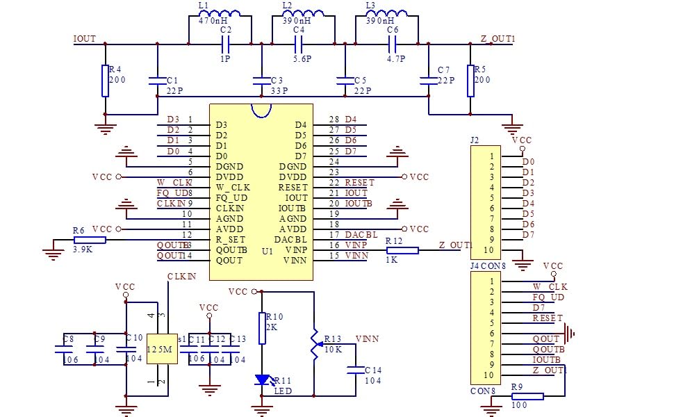
Figure 4.1: Schematic diagram illustrating the internal connections and components of the AD9851 module.
5. Especificaciones
| Parámetro | Valor |
|---|---|
| DDS Chip | Año 9851 d.C. |
| Rango de frecuencia de onda sinusoidal | 0 - 70 MHz |
| Rango de frecuencia de onda cuadrada | 0 - 1 MHz |
| Frecuencia de reloj | Hasta 180 MHz |
| Data Input Modes | Parallel and Serial (jumper selectable) |
| Formas de onda de salida | 2 Sine Wave, 2 Square Wave |
| Dimensiones del paquete | 3.94 x 1.98 x 0.79 pulgadas |
| Peso del artículo | 0.704 onzas |
6. Mantenimiento
To ensure the longevity and optimal performance of your AD9851 DDS Signal Generator Module, follow these maintenance guidelines:
- Manténlo limpio: Limpie el módulo periódicamente con un paño suave y seco. Evite el uso de líquidos o limpiadores abrasivos.
- Evite la descarga estática: Handle the module with care, especially in environments prone to static electricity. Use anti-static precautions when necessary.
- Almacenamiento adecuado: Store the module in a dry, dust-free environment, away from extreme temperatures and direct sunlight.
- Inspeccionar las conexiones: Periodically check all connections for looseness or corrosion.
7. Solución de problemas
If you encounter issues with your AD9851 DDS Signal Generator Module, consider the following troubleshooting steps:
- Sin señal de salida:
- Verify that the module is receiving proper power (VCC and GND).
- Check all data input connections (parallel or serial) and ensure your microcontroller is sending correct commands.
- Confirm the jumper for data input mode is correctly set.
- Ensure the RESET pin is not held low.
- Incorrect Frequency/Waveform:
- Double-check your programming code for the AD9851 chip, especially frequency tuning words.
- Ensure the clock frequency setting in your code matches the module's crystal oscillator.
- For square waves, adjust the onboard potentiometer to see if it affects the output.
- El módulo no responde:
- Apague y encienda el módulo.
- Verifique que todas las conexiones estén seguras y libres de cortocircuitos.
8. Información de garantía
This GODIYMODULES product is covered by a limited warranty against defects in materials and workmanship. The warranty period typically extends for 30 days from the date of purchase. This warranty does not cover damage caused by misuse, accident, unauthorized modification, or improper installation. Please retain your proof of purchase for any warranty claims.
9. Soporte
For technical assistance, further inquiries, or to report issues not covered in this manual, please contact GODIYMODULES customer support. Refer to the product packaging or the retailer's webSitio para obtener información de contacto específica.