
1. Introducción y másview
The JDIAG PB10 Automotive Circuit Tester is a multi-functional diagnostic tool designed to help users quickly and accurately identify and resolve electrical issues in vehicles. It supports a wide range of functions including voltage testing, polarity testing, component activation, continuity testing, grounding tests, diode detection, and short circuit tracing. This manual provides detailed instructions for safe and effective operation of your PB10 circuit tester.

Figure 1.1: JDIAG PB10 Automotive Circuit Tester with included cables and clamps.
2. Características principales
- Multifuncionalidad: Performs Voltage Test, Polarity Test, Component Activation, Continuity Test, Grounding Test, Diode Detection, Test Trailer Lights & Connectors, Trace & Locate Short Circuits, Jumper Function, Quick Self-test, and Overload Protection.
- Amplio Voltage Rango: Suitable for DC 8V to 32V automotive electrical systems, with voltage testing from 0V to 80V.
- Pantalla LED digital: Proporciona un volumen claro y preciso.taglecturas electrónicas.
- Iluminación LED: Equipped with auxiliary LED lights for improved visibility in low-light conditions.
- Zumbador audible: Provides audio feedback for various test results and overload alerts.
- Extended Test Line: Includes a 5-meter (16.41 ft) extended test line for comprehensive vehicle circuit system testing.
- Protección contra sobrecarga: Internal circuit breaker automatically trips and issues a buzzer prompt if current exceeds 8A, protecting the device and user.

Figura 2.1: Sobreview of the JDIAG PB10's multi-function capabilities.
3. ¿Qué hay en la caja?
- JDIAG PB10 Automotive Probe Circuit Tester
- Battery Clip Cable (Red/Black)
- Cl de tierraamp
- 5-meter (16.41 ft) Extended Test Line
- Manual de usuario
4. Configuración
Before using the JDIAG PB10, ensure the vehicle's ignition is off. Connect the power clips to the vehicle's battery terminals. The red clip connects to the positive (+) terminal, and the black clip connects to the negative (-) terminal. The device will power on automatically once connected.

Figure 4.1: Key components of the JDIAG PB10 tester.
Vídeo 4.1: Terminadoview of the JDIAG PB60 (similar to PB10) and its accessories, including setup for use. Note: This video features the PB60 model, but the setup process is similar for the PB10.
5. Instrucciones de funcionamiento
5.1. Vol.tage Prueba
Para probar vol.tage, simply touch the probe tip to the circuit point you wish to measure. The digital LED display will show the voltage reading. The PB10 can measure voltages de 0 V a 80 V CC.

Figura 5.1.1: Realización de un voltage test on a vehicle's fuse box.
5.2. Prueba de polaridad
When the probe detects a positive voltage, the red (+) LED indicator light will illuminate. When it detects a negative voltage, the green (-) LED indicator light will illuminate. This provides quick visual confirmation of circuit polarity.
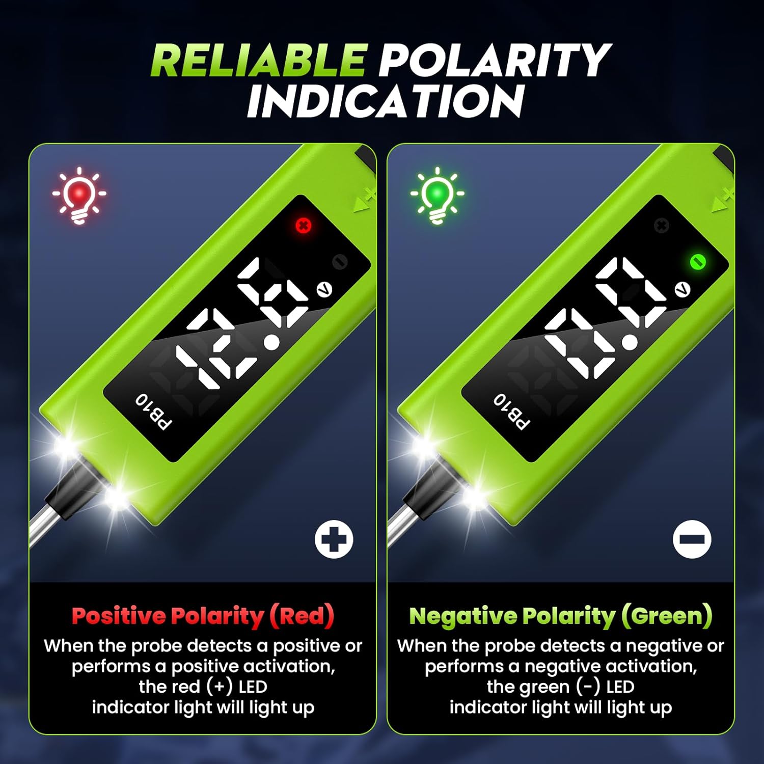
Figure 5.2.1: Visual indication of positive (red) and negative (green) polarity.
5.3. Activación de componentes
The PB10 can activate components by supplying positive or negative battery current to the probe tip. Push the power switch forward to supply positive current, or backward to supply negative current. This function is useful for testing components like starter fuel pumps, solenoid valves, blowers, cooling fans, and headlights.

Figura 5.3.1: Examples of components that can be activated using the PB10.
5.4. Prueba de continuidad
To perform a continuity test, connect the ground clamp to a known good ground. Touch the probe tip to the circuit you want to test. If the circuit is continuous, the green indicator light will turn on and the buzzer will sound. This helps identify open circuits.

Figure 5.4.1: Demonstrating a continuity test with the PB10.
5.5. Grounding Test
The PB10 supports grounding tests to check for bad grounds or power supply failures. Connect the main power clips to the battery. Touch the probe tip to the component or wire you suspect has a bad ground. If a good ground is detected, the green indicator light will illuminate and the buzzer will sound.
5.6. Diode Detection
The device can detect diodes. When testing a diode, the display will show the voltage drop across the diode. This helps in diagnosing faulty diodes within a circuit.

Figure 5.6.1: Using the PB10 for diode detection.
5.7. Test Trailer Lights & Connectors
The extended test line and various functions of the PB10 make it ideal for testing trailer lights and their connectors. You can check for voltage, continuity, and proper grounding in the trailer's electrical system.
5.8. Trace & Locate Short Circuits
The PB10's high sensitivity probe assists in accurately and quickly troubleshooting faulty components and tracing short circuits. By following the circuit path and observing voltage readings and buzzer feedback, you can pinpoint the exact location of a short.

Figure 5.8.1: The PB10 indicating a shorted circuit.
5.9. Jumper Function
The PB10 can act as a jumper to bypass suspected faulty components or provide temporary power to a circuit. Exercise caution when using this function, as it may bypass existing circuit protection.
5.10. Quick Self-test
The device performs a quick self-test upon power-up to ensure proper functionality. This helps confirm the tester is ready for use.
5.11. Protección contra sobrecarga
The PB10 features an internal overload protection device. If the current drawn through the probe exceeds 8A, the circuit breaker will automatically trip, and the buzzer will sound, protecting the device and preventing damage to the vehicle's electrical system. To reset, remove the probe from the circuit and press the power switch to its neutral position.

Figure 5.11.1: The PB10's built-in overload protection.
Video 5.11.2: Demonstration of the JDIAG PB10's various testing capabilities, including voltage and continuity tests.
6. Mantenimiento
- Limpieza: After each use, wipe the probe tip and device body with a clean, dry cloth. Avoid using abrasive cleaners or solvents.
- Almacenamiento: Store the PB10 in a dry, cool place away from direct sunlight and extreme temperatures. Keep it in its original packaging or a protective case to prevent damage.
- Probe Tip Replacement: The probe tip is designed to be durable, but if it becomes damaged or worn, it can be replaced. Refer to the user manual for specific replacement instructions.
- Cuidado de cables: Avoid kinking or sharply bending the cables. Store them neatly to prevent tangles and damage.

Figure 6.1: The PB10 features a replaceable button for easy maintenance.
7. Solución de problemas
- El dispositivo no se enciende:
- Ensure the battery clips are securely connected to the correct positive (+) and negative (-) terminals of the vehicle battery.
- Verify the vehicle battery has sufficient charge (8V-32V DC).
- Volumen inexactotagy Lecturas:
- Check for clean connections at the battery terminals and the probe tip.
- Ensure the probe tip is making good contact with the circuit being tested.
- Compare readings with a known accurate multimeter if available. Note that minor discrepancies (e.g., 0.2V-0.3V) may occur due to cable resistance, which is generally acceptable for automotive testing.
- Overload Protection Tripping Frequently:
- This indicates a short circuit or excessive current draw. Disconnect the device immediately.
- Inspect the circuit for shorts or components drawing more than 8A.
- Ensure you are not accidentally touching the probe tip to a negative pole while in activation mode, as this will trigger overcurrent protection.
- Sin sonido de timbre:
- Check if the buzzer is obstructed or damaged.
- Ensure the test conditions (e.g., continuity) are met for the buzzer to activate.
8. Especificaciones
| Especificación | Valor |
|---|---|
| Vol de entradatage | 8V-32V DC |
| Vol de pruebatage Rango | 0-80V DC |
| Corriente de trabajo | 80 mA |
| Corriente de activación | 0-8A |
| Temperatura de funcionamiento | 0 °C-60 °C (32 °F-140 °F) |
| Temperatura de almacenamiento | -40 ° C-70 ° C (-40 ° F-158 ° F) |
| Dimensiones del producto | 9.06 x 0.94 x 1.18 pulgadas |
| Peso del artículo | 7.09 onzas (201 gramos) |
| Longitud del cable | 5 metros (16.41 pies) |
9. Garantía y soporte
JDIAG is committed to providing high-quality automotive tools. For any product inquiries, technical support, or warranty claims, please contact JDIAG customer service through the Amazon platform or visit the official JDIAG store. Keep your purchase receipt as proof of purchase for warranty purposes.
Para obtener más información y asistencia, visite el JDIAG Store on Amazon.