
Introducción
Welcome to the ULTRICS Digital Multimeter D2 user manual. This device is designed for precise and reliable electrical measurements, suitable for professionals and DIY enthusiasts. It accurately measures AC/DC voltage, DC current, resistance, continuity, and diodes. This manual provides essential information for safe and effective operation, helping you to maximize the utility of your new multimeter.
Información de seguridad
ADVERTENCIA: Always exercise extreme caution when working with electrical circuits. Improper use of this multimeter can result in electric shock, personal injury, or damage to the device.
- No exceda los valores de entrada máximos para ningún rango.
- Do not use the multimeter if it or the test leads appear damaged. Inspect them before each use.
- Ensure the function switch is in the correct position before making measurements. Changing ranges while connected to a live circuit can cause damage.
- Disconnect power to the circuit before measuring resistance, continuity, or diodes.
- Tenga cuidado al trabajar con vol.tages superior a 30 V CA RMS, 42 V pico o 60 V CC. Estos volúmenestages pose a significant shock hazard.
- Always connect the common (COM) test lead first, then the live lead. Disconnect the live lead first, then the common lead.
- Replace the battery when the low battery indicator appears to ensure accurate readings and proper device function.
This multimeter is rated CAT II 600V, indicating its suitability for measurements on circuits directly connected to the low-voltage instalación.
Contenido del paquete
Verifique que todos los artículos estén presentes en el paquete:
- 1 x ULTRICS Digital Multimeter D2
- 2 cables de prueba (rojo y negro)
- Batería 1 x 9V
- 1 x Manual de usuario (este documento)
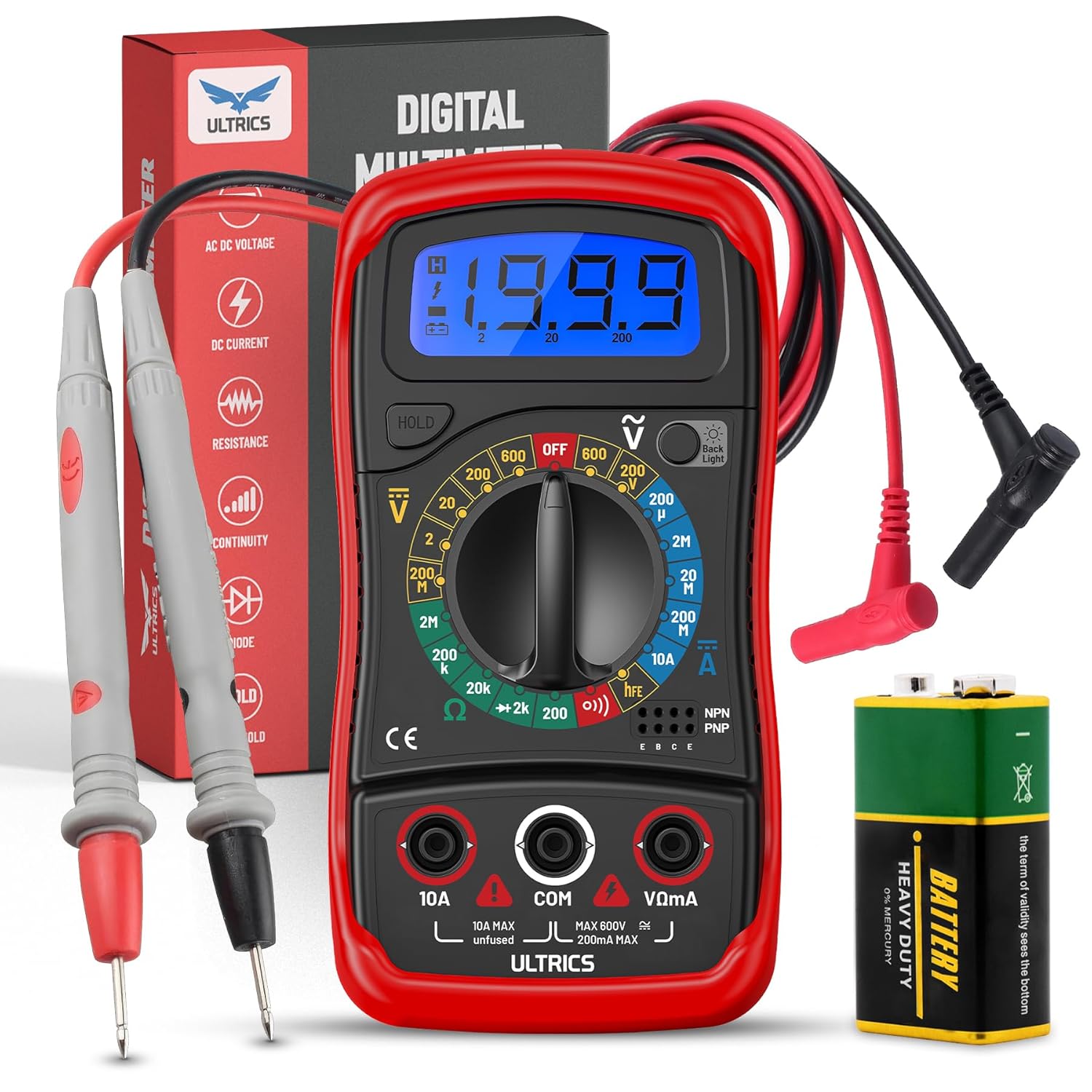
Image: Contents of the ULTRICS Digital Multimeter D2 package, including the multimeter, red and black test leads, and a 9V battery.
Producto terminadoview
Familiarize yourself with the components of your ULTRICS Digital Multimeter D2.

Image: Detailed diagram of the ULTRICS Digital Multimeter D2, highlighting its key components such as the LCD display, data hold button, backlight button, function switch, test lead jacks, and protective rubber shell.
- Pantalla LCD: Shows measurement readings, units, and polarity. Features a bright backlight for low-light conditions.
- Botón de retención de datos: Freezes the current reading on the display for easier recording.
- Botón de retroiluminación: Activa o desactiva la luz de fondo de la pantalla.
- Function Switch (Rotary Dial): Selecciona la función y el rango de medición deseados.
- Conector de entrada de 10 A: Used for measuring DC current up to 10 AmpEres.
- COM (Common) Input Jack: The negative (-) input for all measurements. Always connect the black test lead here.
- Conector de entrada VΩmA: The positive (+) input for voltage, resistencia y miliampere current measurements. Connect the red test lead here.
- Transistor Test Jacks (hFE): Used for testing NPN and PNP transistors.
- Protective Rubber Shell: Provides durability and protection against minor impacts and splashes.
- Pata de cabra plegable: Permite una operación con manos libres y fácil viewángulo de ing.
Configuración
Instalación de la batería
The ULTRICS Digital Multimeter D2 requires one 9V battery (included).
- Ubique el compartimiento de la batería en la parte posterior del multímetro.
- Utilice un destornillador para quitar el tornillo que fija la tapa de la batería.
- Retire con cuidado la tapa de la batería.
- Conecte la batería de 9 V a las pinzas de la batería, asegurándose de que la polaridad sea correcta (+ a + y - a -).
- Coloque la batería dentro del compartimento.
- Vuelva a colocar la tapa de la batería y asegúrela con el tornillo.
Conexión de cables de prueba
Asegúrese siempre que los cables de prueba estén conectados de forma segura antes de tomar medidas.
- Insert the black test lead's banana plug into the COM Toma de entrada (común).
- Para la mayoría de las mediciones (voltage, resistance, continuity, diode, small current), insert the red test lead's banana plug into the VΩmA toma de entrada.
- For high current measurements (up to 10A DC), insert the red test lead's banana plug into the 10A toma de entrada.
Instrucciones de funcionamiento
Esta sección detalla cómo realizar diversas mediciones utilizando su multímetro.
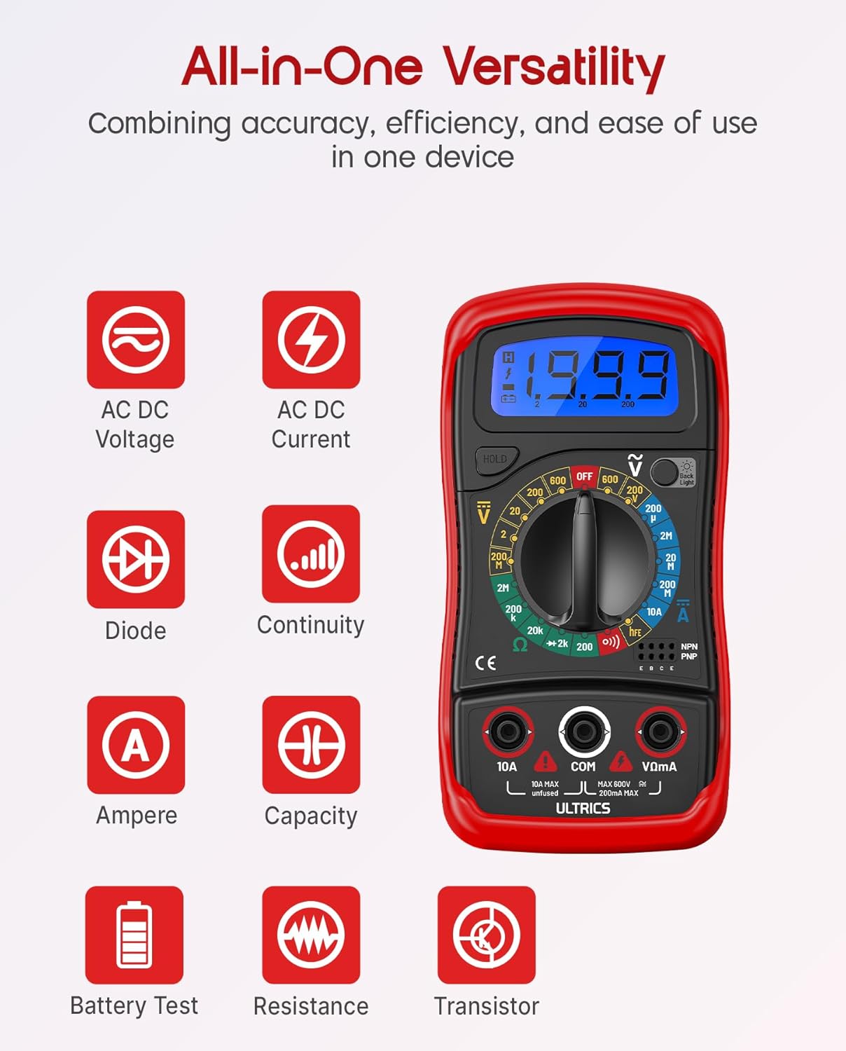
Image: Visual representation of the multimeter's versatile functions, including AC/DC Voltage, AC/DC Current, Diode, Continuity, Ampere, Capacity, Battery Test, Resistance, and Transistor measurements.
Medición de DC Voltage (VCC)
- Conecte el cable de prueba negro al COM Jack y el cable de prueba rojo a la VΩmA Jacobo.
- Turn the function switch to the desired VDC range (e.g., 200mV, 2V, 20V, 200V, 600V). If unsure, start with the highest range and decrease as needed.
- Conecte los cables de prueba en paralelo a través del componente o circuito que se va a medir.
- Leer el vol.tage valor en la pantalla LCD.
Medición de CA Voltage (VCA)
- Conecte el cable de prueba negro al COM Jack y el cable de prueba rojo a la VΩmA Jacobo.
- Turn the function switch to the desired VACACIONES range (e.g., 200V, 600V).
- Conecte los cables de prueba en paralelo a través del voltaje de CA.tagy fuente.
- Leer el vol.tage valor en la pantalla LCD.
Measuring DC Current (ADC)
PRECAUCIÓN: Never connect the multimeter in parallel when measuring current. Always connect it in series with the circuit. Improper connection can damage the multimeter or the circuit.
- Apague la alimentación al circuito.
- Para corrientes de hasta 200 mA, conecte el cable de prueba negro a la COM Jack y el cable de prueba rojo a la VΩmA Jacobo.
- Para corrientes de hasta 10 A, conecte el cable de prueba negro a la COM Jack y el cable de prueba rojo a la 10A Jacobo.
- Turn the function switch to the desired Conductor adverso range (e.g., 200µA, 2mA, 20mA, 200mA, 10A).
- Rompa el circuito y conecte el multímetro en serie con el circuito.
- Encienda el circuito.
- Lea el valor actual en la pantalla LCD.
- Turn off power to the circuit before disconnecting the multimeter.
Medición de la resistencia (Ω)
PRECAUCIÓN: Ensure the circuit is completely de-energized before measuring resistance. Measuring resistance on a live circuit can damage the multimeter.
- Conecte el cable de prueba negro al COM Jack y el cable de prueba rojo a la VΩmA Jacobo.
- Turn the function switch to the desired Ω range (e.g., 200Ω, 2kΩ, 20kΩ, 200kΩ, 2MΩ, 20MΩ).
- Conecte los cables de prueba al componente cuya resistencia desea medir.
- Lea el valor de resistencia en la pantalla LCD.
Prueba de continuidad
The continuity test checks for a complete circuit path. An audible buzzer will sound if continuity is detected.
- Conecte el cable de prueba negro al COM Jack y el cable de prueba rojo a la VΩmA Jacobo.
- Gire el interruptor de función a la Continuidad (buzzer) position.
- Conecte los cables de prueba a través del circuito o componente.
- Si la resistencia es inferior a aproximadamente 50 Ω, sonará el zumbador, indicando continuidad.
Prueba de diodo
La prueba de diodo mide el vol directo.tagy la gota de un diodo.
- Conecte el cable de prueba negro al COM Jack y el cable de prueba rojo a la VΩmA Jacobo.
- Gire el interruptor de función a la Diodo posición.
- Connect the red test lead to the anode (+) and the black test lead to the cathode (-) of the diode.
- Leer el vol adelantetage drop on the LCD display. Reverse the leads; the display should show "OL" (Overload) for a good diode.
Prueba de transistor hFE
This function tests the DC current gain (hFE) of NPN and PNP transistors.
- Gire el interruptor de función a la alta fe posición.
- Identify the Emitter (E), Base (B), and Collector (C) leads of the transistor.
- Insert the transistor leads into the corresponding holes in the alta fe socket on the multimeter, ensuring correct NPN or PNP type.
- Lea el valor hFE en la pantalla LCD.
Función de retención de datos
Presione el SOSTENER Botón para congelar la lectura actual en la pantalla. Presiónelo de nuevo para liberar la retención y reanudar las lecturas en tiempo real.
Función de luz de fondo
Presione el Iluminar desde el fondo button to turn the LCD backlight on or off, improving visibility in dim environments.

Imagen: Un primer plano view of the multimeter's LCD display, demonstrating its bright backlight feature for enhanced readability in various lighting conditions.
Mantenimiento
Limpieza
Para limpiar el multímetro, limpie la carcasa con un paño.amp cloth and a mild detergent. Do not use abrasives or solvents, as these may damage the casing o pantalla.
Reemplazo de batería
When the low battery indicator appears on the display, replace the 9V battery as described in the "Installing the Battery" section to ensure continued accurate readings.
Reemplazo de fusibles
If the current measurement function stops working, the fuse may need replacement. This multimeter is equipped with internal fuses for protection.
- Asegúrese de que el multímetro esté apagado y que todos los cables de prueba estén desconectados.
- Retire la tapa de la batería y la batería.
- Carefully open the main casing (this may require removing additional screws, typically located under the rubber shell).
- Locate the fuse(s) on the circuit board. This model typically uses a 200mA/250V fuse for the mA range and a 10A/250V fuse for the 10A range.
- Replace the blown fuse with a fuse of the same type and rating. Never use a fuse with a different rating.
- Reassemble the multimeter, ensuring all screws are tightened and the casing is properly sealed.
Almacenamiento
If the multimeter is not used for a long period, remove the battery to prevent leakage and store the device in a cool, dry place, away from direct sunlight and extreme temperatures.
Solución de problemas
| Problema | Posible causa | Solución |
|---|---|---|
| Sin pantalla o pantalla tenue | Batería muerta o baja | Reemplace la batería de 9V. |
| Se muestra "OL" (Sobrecarga) | Input value exceeds selected range; open circuit (for resistance/continuity) | Select a higher range; check for breaks in the circuit or component. |
| Lecturas incorrectas | Incorrect function/range selected; poor test lead connection; low battery | Verify function switch position and range; ensure leads are firmly connected; replace battery. |
| La medición actual no funciona | Fusible fundido | Reemplace el fusible apropiado (consulte la sección Mantenimiento). |
| No hay zumbador de continuidad | Open circuit; resistance too high | Ensure circuit is closed; check resistance value (buzzer typically activates below 50Ω). |
Presupuesto
| Característica | Detalle |
|---|---|
| Modelo | Digital Multimeter D2 |
| Mostrar | 3 ½ digit LCD, 1999 counts, with backlight |
| Vol DCtage | 200 mV / 2 V / 20 V / 200 V / 600 V |
| Vol. CAtage | 200 V / 600 V |
| Corriente continua | 200 µA / 2 mA / 20 mA / 200 mA / 10 A |
| Resistencia | 200Ω / 2kΩ / 20kΩ / 200kΩ / 2MΩ / 20MΩ |
| Prueba de diodo | Sí |
| Zumbador de continuidad | Sí |
| Prueba de transistor hFE | Sí |
| Retención de datos | Sí |
| Fuente de poder | Batería de 9 V |
| Clasificación de seguridad | IEC CAT II 600V, CE, RoHS compliant |
| Dimensiones (L x An x Al) | 14.6 x 10 x 5 cm (5.75 x 3.94 x 1.97 pulgadas) |
| Peso | 240 gramos (0.53 lbs) |
Garantía y soporte
ULTRICS provides a 12-month warranty for this product, covering manufacturing defects from the date of purchase. Please retain your proof of purchase for warranty claims.
For technical support, warranty claims, or any questions regarding your ULTRICS Digital Multimeter D2, please contact ULTRICS customer service through the retailer's platform or the official ULTRICS webSitio. Tenga a mano los detalles de su compra y el número de modelo al contactar con el servicio de asistencia.
Fabricante: ULTRICOS
Número de modelo: Digital Multimeter D2
ASIN: B0DYP62MW7