1. Introducción
This manual provides essential information for the safe and efficient installation, operation, and maintenance of the HLTNC HS320 Variable Frequency Drive (VFD) Inverter. The HS320 is designed to control the speed of three-phase AC motors, commonly used in applications such as spindle speed control. Please read this manual thoroughly before using the product to ensure proper functionality and safety.
2. Información de seguridad
WARNING: Improper installation or operation can lead to serious injury or equipment damage. Always follow safety guidelines.
- Peligro eléctrico: Ensure all power is disconnected from the supply before performing any installation, wiring, or maintenance. Wait at least 10 minutes after disconnecting power for capacitors to discharge before touching internal components.
- Toma de tierra: Always ensure the VFD is properly grounded according to local electrical codes.
- Personal calificado: Installation and maintenance should only be performed by qualified electrical personnel.
- Ambiente: Do not operate the VFD in environments with excessive dust, moisture, corrosive gases, or direct sunlight. Mount the inverter on a non-combustible surface.
- Protección contra sobrecarga: Do not bypass any safety or overload protection features.
Refer to the warning labels on the device for additional safety instructions.

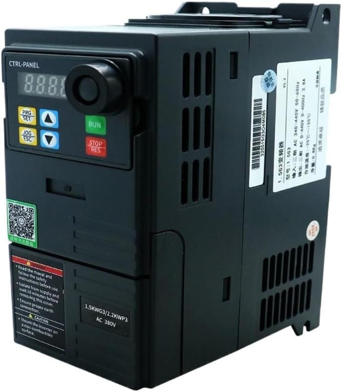
3. Producto terminadoview
The HLTNC HS320 is a compact Variable Frequency Drive designed for precise motor speed control. It features a digital display, control buttons, and a rotary encoder for parameter adjustment. The unit is equipped with various input/output terminals for external control and monitoring.


4. Especificaciones
The following table outlines the key technical specifications for the HLTNC HS320 VFD (0.75KW, 380V, 0-400Hz variant).
| Característica | Especificación |
|---|---|
| Número de modelo | HS320 |
| Vol de entradatage | 380 V CA |
| Potencia de salida | 0.75KW |
| Fase de salida | Trifásico |
| Rango de frecuencia de salida | 0-400 Hz |
| Tipo | Inversor CC/CA |
| Método de control | Vector Control / V/F Control (refer to detailed parameter settings) |
| Método de enfriamiento | Enfriado por ventilador |
| Temperatura de funcionamiento | Generalmente de -10 °C a 40 °C (de 14 °F a 104 °F) |
| Humedad | Menos del 90% de humedad relativa, sin condensación |
| Altitud | Below 1000m (3300ft) |
| Nivel de protección | IP20 (typical for enclosed VFDs) |
| Dimensiones físicas y peso | Refer to product packaging or official documentation for accurate physical dimensions and weight. |
5. Instalación
5.1 Montaje
- Mount the VFD vertically on a sturdy, non-combustible surface.
- Ensure adequate ventilation space around the unit (typically 10cm above and below, 5cm on sides) for proper heat dissipation.
- Avoid mounting in direct sunlight, near heat sources, or in areas subject to vibration.
- Use appropriate screws and mounting hardware to secure the VFD firmly.
5.2 Cableado
All wiring must comply with local and national electrical codes. Use appropriate wire gauges for the VFD's power rating.
5.2.1 Power Input (R, S, T)
- Connect the 380V AC three-phase power supply to the R, S, and T terminals.
- Install an appropriate circuit breaker or fuse upstream for protection.
5.2.2 Motor Output (U, V, W)
- Connect the three-phase motor to the U, V, and W output terminals.
- Ensure the motor's rated voltage and current are compatible with the VFD.
5.2.3 Grounding (PE)
- Connect the VFD's grounding terminal (PE) to a reliable earth ground. This is critical for safety and EMI reduction.
5.2.4 Terminales de control
The VFD provides various control terminals for external start/stop, speed reference (analog input), multi-function inputs, and relay outputs. Refer to the detailed wiring diagram in the full product manual for specific terminal assignments and functions. Common connections include:
- Entrada analogica: For external speed control via potentiometer or 0-10V/4-20mA signal.
- Entradas digitales: For external start, stop, forward/reverse, multi-step speed commands.
- Salidas de relé: For fault indication or run status.
6. Operación
6.1 Funciones del panel de control
The integrated control panel allows for direct operation and parameter setting.
- Pantalla digital: Muestra frecuencia, corriente de salida, vol.tage, and parameter codes.
- Botón EJECUTAR: Arranca el motor.
- STOP/RES Button: Stops the motor or resets a fault.
- PRG/SET Button: Enters/exits parameter setting mode, confirms parameter changes.
- JOG/ESC Button: Initiates JOG operation (momentary run) or exits a menu without saving.
- Flechas arriba/abajo: Navegar a través de los parámetros o ajustar valores.
6.2 Pasos básicos de operación
- Encendido: Conecte la alimentación al VFD. La pantalla se iluminará.
- Establecer frecuencia: Use the Up/Down arrows to set the desired output frequency.
- Motor de arranque: Presione el CORRER Botón. El motor acelerará a la frecuencia establecida.
- Detener el motor: Presione el PARAR/RESULTAR Botón. El motor desacelerará y se detendrá.
7. Configuración de parámetros
The HLTNC HS320 VFD has a comprehensive set of parameters to customize its operation. Accessing and modifying these parameters allows fine-tuning for specific applications.
7.1 Entering Parameter Mode
- Presione el PRG/SET button to enter parameter setting mode. The display will show a parameter group code (e.g., P00).
- Use the Up/Down arrows to navigate through parameter groups (e.g., P00, P01, P02, etc.).
- Prensa PRG/SET again to enter a specific parameter within a group (e.g., P00.01).
7.2 Modificación de parámetros
- Once a specific parameter is selected, use the Up/Down arrows to change its value.
- Prensa PRG/SET to save the new value. The display may flash to confirm.
- Prensa JOG/ESC to exit the current parameter or group without saving changes.
7.3 Important Parameters (Examplos)
- P00.01 (Max Output Frequency): Sets the maximum frequency the VFD can output.
- P00.03 (Acceleration Time): Defines the time it takes for the motor to accelerate from 0Hz to the maximum frequency.
- P00.04 (Deceleration Time): Defines the time it takes for the motor to decelerate from the maximum frequency to 0Hz.
- P00.05 (Rated Motor Frequency): Set to the motor's nominal frequency.
- P00.06 (Rated Motor Voltagmi): Set to the motor's nominal voltage.
- P00.07 (Rated Motor Current): Set to the motor's nominal current.
For a complete list of parameters and their detailed descriptions, refer to the comprehensive parameter manual provided with your HLTNC HS320 VFD.
8. Mantenimiento
El mantenimiento regular garantiza la longevidad y el funcionamiento confiable de su VFD.
- Limpieza: Limpie periódicamente el exterior y las aletas de refrigeración del VFD para evitar la acumulación de polvo, que puede dificultar la disipación del calor. Utilice un paño suave y seco. No utilice líquidos ni disolventes.
- Inspección del ventilador: Check the cooling fan for proper operation and ensure it is free from obstructions. Replace if noisy or not functioning.
- Estanqueidad del terminal: Revise periódicamente el apriete de todos los terminales del cableado. Las conexiones flojas pueden causar sobrecalentamiento y funcionamiento intermitente.
- Comprobación ambiental: Asegúrese de que el entorno operativo permanezca dentro de los rangos de temperatura y humedad especificados.
9. Solución de problemas
This section provides solutions for common issues. For complex problems, contact technical support.
| Código de problema/error | Posible causa | Solución |
|---|---|---|
| Sin pantalla/energía | Sin alimentación de entrada; Fusible quemado; Fallo interno. | Check power supply and fuses. If power is present, contact support. |
| El motor no funciona | VFD not in RUN mode; Incorrect frequency setting; Motor wiring issue; Fault condition. | Press RUN. Check frequency setting. Verify motor wiring. Check for fault codes. |
| Overcurrent Fault (OC) | Sobrecarga del motor; Cortocircuito en el cableado del motor; Aceleración/desaceleración rápida. | Reduce load. Check motor wiring. Increase acceleration/deceleration times (P00.03/P00.04). |
| sobrevoltajetage Fault (OV) | Regenerative braking from motor; High input voltage. | Increase deceleration time. Check input voltage. Consider braking resistor if needed. |
| bajovoltage Fault (UV) | Bajo volumen de entradatage; Power sag. | Compruebe el volumen de la fuente de alimentación de entradatage. |
| Overheat Fault (OH) | Insufficient ventilation; High ambient temperature; Clogged fan. | Ensure proper ventilation. Clean cooling fins and fan. Reduce ambient temperature. |
Presiona siempre el PARAR/RESULTAR button to clear a fault after addressing the cause.
10. Garantía y soporte
For warranty information, technical support, or service inquiries, please refer to the documentation provided with your purchase or contact your vendor. Ensure you have your product model number (HS320) and purchase details available when seeking support.


