
Wattive GYAR9-AC-G 2P 40A Automatic Reclosing RCCB Circuit Breaker User Manual
Modelo: GYAR9-AC-G
Brand: Wattive
1. Producto terminadoview
The Wattive GYAR9-AC-G is an intelligent 2-pole, 40A Residual Current Circuit Breaker (RCCB) with an automatic reclosing function. Designed for AC230V systems, it features a digital display and a 300mA leakage protection value. This device automatically recloses the circuit after an accidental trip, reducing manual intervention and improving system efficiency. It supports both automatic and manual operating modes.
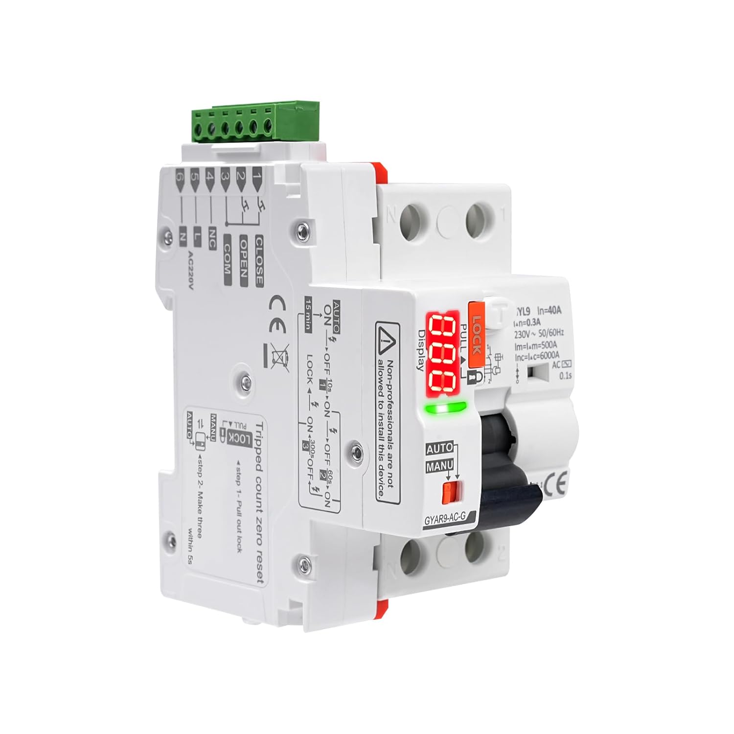
Imagen 1.1: Frente view of the Wattive GYAR9-AC-G Automatic Reclosing RCCB Circuit Breaker, showing its compact design, digital display, and control switches.
2. Información de seguridad
ADVERTENCIA: Installation and maintenance of this device must be performed by qualified electricians only. Failure to follow these instructions can result in electric shock, fire, or serious injury.
- Always disconnect power before installing, wiring, or servicing the circuit breaker.
- Asegúrese de que haya una conexión a tierra adecuada según los códigos eléctricos locales.
- No opere el dispositivo si parece dañado.
- Verifique que todas las conexiones sean seguras y correctas antes de restablecer la energía.
- The device is designed for indoor use in environments within specified temperature and humidity ranges.
3. Características del producto
The GYAR9-AC-G circuit breaker incorporates several advanced features for enhanced safety and operational efficiency:
- Intelligent Automatic Reclosing: Automatically restores power after an accidental trip, minimizing downtime.
- Automatic/Manual Switching: Allows selection between automatic reclosing and manual restoration modes.
- Self-Locking Mode: Engages after multiple consecutive faults to ensure circuit safety before manual reset.
- Pantalla LED digital: Provides real-time status, fault codes, reclosing counts, and countdown timers.
- Construcción de alta calidad: Made from PC material with an IP20 protection grade.
- Instalación en riel DIN: Compatible with standard 35mm DIN rails.

Imagen 3.1: Visual representation of the key features, including PC material, IP20 protection, DIN rail installation, digital display, two switching modes, and LED indicator.
4. Especificaciones
| Parámetro | Valor |
|---|---|
| Material | Policarbonato (PC) |
| Vol de suministrotage | CA 230 V |
| Corriente nominal | 40 A |
| Frecuencia de funcionamiento | 50/60 Hz |
| Valor de protección contra fugas | 300 mA |
| Señal de control | Automatic Reclosing + Dry Contact Control |
| Pantalla digital | 3-digit interruption code, reclosing count, countdown |
| Duración efectiva de la señal de control | > 400 ms |
| Hora de cierre | < 1 s |
| Horario de apertura | < 0.5 s |
| Longitud del cable de control | ≤ 1500 m |
| Consumo de energía | ≤ 1.5 VA (static), ≤ 25 VA (dynamic) |
| Vol. De aislamiento nominaltage | 400 V |
| Vol nominal de resistencia al impulsotage (Uimp) | 4 kV (4.9 kV at sea level) |
| Vida eléctrica | 10,000 cycles, 3 cycles/min |
| Vida mecánica | 10,000 ciclos |
| Clase de protección | IP20 |
| Temperatura ambiente | -25 a +70 °C |
| Temperatura de almacenamiento | -40 a +70 °C |
| Wiring Capacity (Power/Control Terminals) | 28-12 AWG (2.5 mm²) |
| Wiring Capacity (Auxiliary Signal Terminals) | 28-14 AWG (1.5 mm²) |
| Montaje | DIN Rail EN 60715 (35 mm) |
| Dimensiones (aprox.) | 12 x 11.5 x 9 cm |
| Peso (aprox.) | 351 gramos |

Imagen 4.1: Detailed diagram showing the physical dimensions of the circuit breaker and a summary table of its key operational parameters.
5. Instalación y cableado
The GYAR9-AC-G circuit breaker is designed for DIN rail mounting. Ensure all wiring is performed by a qualified professional in accordance with national and local electrical codes.
5.1. Montaje
- Ensure the power supply to the distribution box is completely disconnected.
- Attach the circuit breaker securely onto a standard 35mm DIN rail.
5.2. Diagrama de cableado
Refer to the wiring diagram below for correct connection of the circuit breaker to the main power supply and loads. The diagram illustrates connections for the Line (L) and Neutral (N) inputs, as well as connections to multiple load circuits.
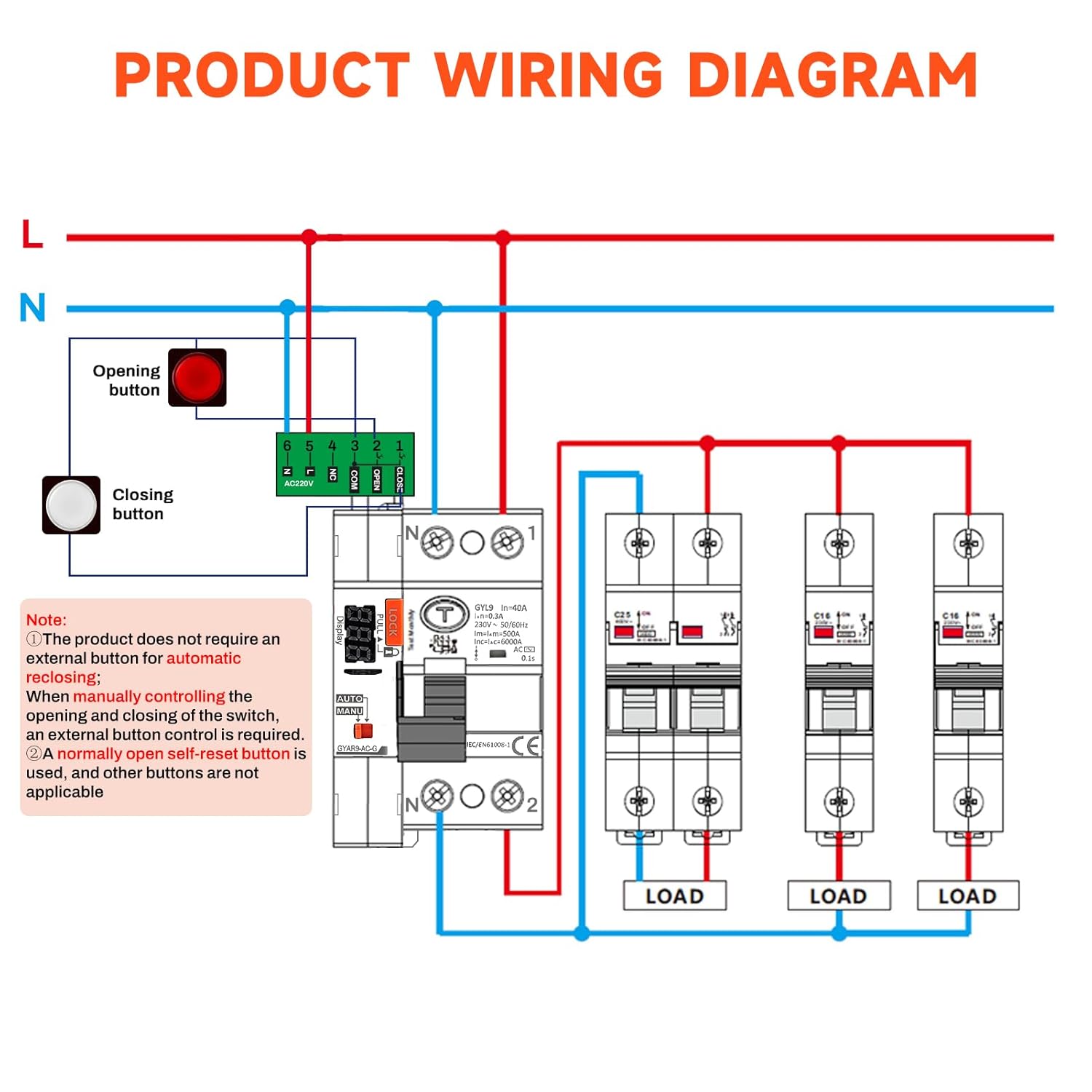
Imagen 5.1: Detailed wiring diagram showing the connection points for the main power supply (L, N), the circuit breaker, and multiple downstream loads. It also indicates optional external opening and closing buttons.
- Connect the main Line (L) and Neutral (N) wires to the designated terminals on the circuit breaker.
- Connect the load circuits to the output terminals.
- For manual control, an external normally open reset button can be connected to the auxiliary signal terminals (28-14 AWG, 1.5 mm²). The product does not require an external button for automatic reclosing.
- Asegúrese de que todas las conexiones estén bien ajustadas y aisladas adecuadamente.
6. Instrucciones de funcionamiento
The GYAR9-AC-G offers both automatic and manual operating modes, selectable via a switch on the device.
6.1. Automatic/Manual Switching Modes
The device features an AUTO/MANU selector switch. The 'LOCK' mechanism prevents accidental operation when engaged.
- Modo automático: In this mode, the circuit breaker will automatically attempt to reclose after a fault trip. The digital display will show a red flashing light when the gate is open and a green flashing light when the gate is closing.
- Modo MANU: In this mode, the circuit breaker requires manual restoration after a fault trip. The yellow light on the display will remain on for manual opening and closing.
- Función LOCK: When the 'LOCK' switch is engaged (pulled out), the circuit breaker cannot be closed, ensuring electrical safety during maintenance or inspection and preventing accidental contact.

Imagen 6.1: De cerca view of the circuit breaker's controls, highlighting the leakage switch, safety lock, broken code display, LED digital display, working mode selection (AUTO/MANU), and operating handle. A table explains the automatic/manual switching and corresponding LED digital display behaviors.
6.2. Self-Locking Mode
To prevent continuous reclosing into a persistent fault, the device enters a self-locking mode after multiple consecutive trips:
- First Fault: The circuit breaker automatically recloses after 9 seconds.
- Second Fault: The circuit breaker automatically recloses after 59 seconds.
- Third Fault: The circuit breaker automatically recloses after 299 seconds.
- Fourth Fault: After the fourth consecutive fault, the recloser enters self-locking mode. Manual intervention is required. The circuit must be checked for safety, and then the gate must be manually reopened.
After 40 seconds of self-locking, the device will automatically recover and be ready for manual or automatic operation again, provided the fault has been cleared.

Imagen 6.2: Illustration of the self-locking mode, showing the digital display countdowns for the first three reclosing attempts and the final self-locking state after the fourth fault.
6.3. Información de la pantalla digital
The 3-digit digital display provides critical operational feedback:
- Interruption Code: Displays a code indicating the type of interruption.
- Reclosing Count: Shows the number of times the circuit has been opened and reclosed.
- Contador regresivo: Indicates the remaining time until the next automatic reclosing attempt or recovery from self-locking mode.
- Indicador LED: Green for normal operation, red for MCB overcurrent error.
7. Mantenimiento
El mantenimiento regular garantiza la longevidad y el funcionamiento confiable de su disyuntor.
- Inspección visual: Inspeccione periódicamente el dispositivo para detectar cualquier signo de daño físico, decoloración o conexiones sueltas.
- Limpieza: Mantenga el dispositivo limpio y libre de polvo y residuos. Utilice un paño seco y suave para limpiarlo. No utilice limpiadores líquidos.
- Botón de prueba: Press the 'Test Monthly' button (if available) regularly to verify the leakage protection function. Follow the instructions on the device for testing.
- Control profesional: Have a qualified electrician inspect the device and electrical system annually.
8. Solución de problemas
Si el disyuntor no funciona como se espera, considere lo siguiente:
- Device in Self-Locking Mode: If the device has tripped multiple times and is not reclosing, it may be in self-locking mode. Check the circuit for faults and manually reset the breaker.
- Sin energía: Verify the main power supply to the distribution box.
- Modo incorrecto: Ensure the AUTO/MANU switch is in the desired position. If in MANU mode, manual reset is required.
- Falla persistente: If the breaker trips immediately after reclosing, there is a persistent fault in the circuit. Disconnect power and have a qualified electrician inspect the wiring and connected loads.
- Error de pantalla digital: Note any error codes displayed and consult a qualified electrician.
9. Áreas de aplicación
The Wattive GYAR9-AC-G intelligent circuit breaker is suitable for a wide range of applications requiring reliable electrical protection and automatic fault recovery:
- Photovoltaic grid-connected AC distribution boxes
- Unmanned mobile phone base stations
- Ascensores
- Smart homes
- Fábricas inteligentes
- New energy vehicle charging stations

Imagen 9.1: Collage of images depicting various application environments for the circuit breaker, including mobile phone base stations, solar power installations, electric vehicle charging points, and smart factory settings.
10. Garantía y soporte
Specific warranty information is not provided in this manual. Please refer to the product packaging or contact your retailer or the manufacturer, Wattive, for details regarding warranty coverage and technical support.
For technical assistance or inquiries, please visit the official Wattive websitio o comuníquese con su departamento de servicio al cliente.