
Introducción
The Luqeeg Signal Generator is a versatile device designed for generating DC voltage and current outputs, as well as PWM pulse square waves. It also features input measurement capabilities, making it suitable for a wide range of applications including PLC controller testing, LED calibration, and general electronic circuit analysis. This manual provides detailed instructions for the proper setup, operation, and maintenance of your signal generator.
1. Configuración y uso inicial
1.1 Desembalaje
Retire con cuidado todos los componentes del embalaje. El paquete debe contener:
- 1 x Signal Generator
- 4 x Clips
- 1 x cable USB
- 1 x Manual de usuario (este documento)
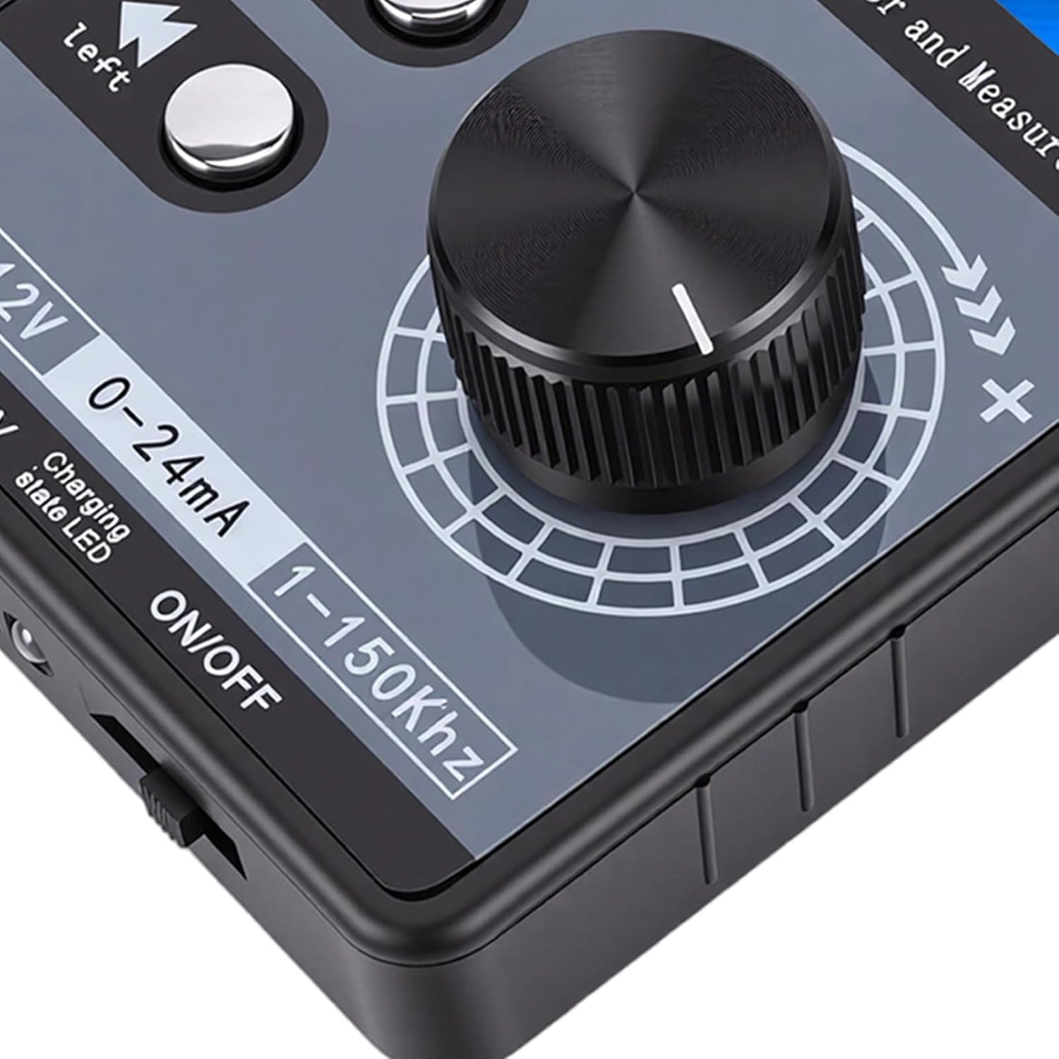
Figura 1.1: Included alligator clips for connections.
1.2 Dispositivo sobreview
Familiarize yourself with the main components of the signal generator:

Figura 1.2: Signal Generator Component Diagram.
- Pluggable terminal block (3.81-9P)
- Símbolo de terminal
- 2 inch TFT color display screen
- Tecla de flecha hacia abajo
- Digital encoder adjustment knob (with button, can be pressed)
- Tecla de mayúsculas izquierda
- Interruptor de encendido
- Luz indicadora de carga
- Puerto USB
1.3 Opciones de fuente de alimentación
The signal generator offers flexible power supply methods:
- External 24VDC Terminal: Connect a 24VDC power source to the designated terminals.
- USB tipo C: Use the provided USB Type-C cable to connect to a power adapter or computer.
- Rechargeable Li Battery: The device supports an internal rechargeable lithium battery (not included). When a battery is installed, it can be charged via USB Type-C or external 24VDC while in use.

Figura 1.3: Multiple power supply methods for the signal generator.
1.4 Diagrama de conexión
Refer to the following diagram for proper terminal connections. Terminal numbers are read from left to right (1-9).

Figura 1.4: Terminal Connection Diagram.
- Tierra (1): Power supply negative (input). This is the same as 9-GND and can be arbitrarily connected.
- 24 V (2): Power supply positive (input). External power input to power or charge the meter.
- mA i (3): Current signal input positive.
- Vi (4): Volumentage signal input positive.
- LP+ (5): EXT 24V input (passive mode).
- mA o (6): Current signal output positive. The current output is commonly used in active mode. The output of the meter 6-mAo 9-GND corresponds to positive and negative current input of the PLC.
- Vo (7): Volumentage signal output positive. The voltage salida 7-Vo 9-GND corresponds to the positive and negative voltage input of the PLC, or it can be measured directly with a multimeter.
- PWM (8): PWM output positive.
- Tierra (9): Signal common ground (internal connect to ①-GND).
Current Sink Two-Wire Output: Conectar el 24V + hacia 5-LP+ terminal of the meter head, and output from the 6-mAo terminal to control the current of the external 24V. The meter head is equivalent to a variable resistor, so it is called passive mode. Direct measurement cannot detect the current, and it can be directly replaced with a passive two-wire pressure/temperature sensor, etc.
2. Instrucciones de funcionamiento
2.1 Interfaz de usuario y pantalla
The device features a 2.0-inch TFT color screen (320x240) that displays all values clearly on one screen. It supports both Chinese and English interface switching. The large digital encoder knob allows for easy and precise adjustments.

Figura 2.1: TFT Color Screen Display.

Figura 2.2: Digital Encoder Adjustment Knob.
2.2 Vol. CCtage y salida de corriente
- Volumentage DC Analog Output Range: ±12V (with short circuit protection).
- Current DC Analog Output Range: 0-24mA (short circuit protected).
- Ajuste de salida: Users can freely set the output range, such as 0-20mA, 4-20mA, 0-10V, 0-5V, etc. The corresponding engineering display values can also be set.
2.3 PWM Pulse Square Wave Output
- Frecuencia ajustable: 1-150 kHz.
- Adjustable Duty Cycle: 0-100%.
- Nivel alto: 5 V.
- Solicitud: PWM pulse output high level is 5V, low level is 0V. It can directly drive buzzers, LEDs, optocouplers, etc., or connect to 12V/24V systems through external level conversion modules.

Figura 2.3: Signal generator connected and operating.
2.4 Input Measurement
- Volumentage Rango de medición: ±50 V.
- Rango de medición actual: ±50mA.
3. Mantenimiento
To ensure the longevity and optimal performance of your Luqeeg Signal Generator, follow these maintenance guidelines:
- Limpieza: Use a soft, dry cloth to clean the device. Avoid using abrasive cleaners or solvents, which can damage the casing o pantalla.
- Almacenamiento: Guarde el dispositivo en un lugar fresco y seco, alejado de la luz solar directa, temperaturas extremas y alta humedad.
- Manejo: Handle the device with care to prevent physical damage. Avoid dropping it or exposing it to strong impacts.
- Battery Care (if installed): If using a rechargeable Li battery, ensure it is charged regularly, even if not in frequent use, to maintain battery health. Do not expose the battery to extreme heat or puncture it.
- Película protectora: The surface protective film of the sticker can be peeled off for clearer viewEn.
4. Solución de problemas
This section addresses common issues you might encounter with your signal generator.
- El dispositivo no se enciende:
- Compruebe si el interruptor de encendido está en la posición "ON".
- Ensure the USB Type-C cable is securely connected and the power source is active.
- If using external 24VDC, verify the power supply is connected correctly to the terminals and is providing the correct voltage.
- If using a rechargeable battery, ensure it is charged.
- Sin señal de salida:
- Verify that the output parameters (voltage, current, PWM frequency, duty cycle) are set correctly on the display.
- Check all connections to the output terminals for proper contact.
- Asegúrese de que el dispositivo esté encendido y funcionando.
- Lecturas de salida incorrectas:
- Confirm that the measurement range is appropriate for the signal being measured.
- Check the calibration settings if custom ranges have been configured.
- Asegúrese de que todas las conexiones sean seguras y libres de interferencias.
- PWM Output Compatibility:
Nota: The PWM output of this device is not suitable for 12V or 2V systems, as 5V is regarded as a low level in these systems. For such applications, an external level conversion module is required.
5. Especificaciones técnicas
| Característica | Especificación |
|---|---|
| Material del producto | abdominales |
| Volumentage DC Analog Output Range | ±12V (with Short Circuit Protection) |
| Volumentage Rango de medición | ±50 V |
| Current DC Analog Output Range | 0-24mA (Short Circuit Protected) |
| Rango de medición actual | ± 50mA |
| PWM Pulse Square Wave Output Frequency | 1-150 kHz (ajustable) |
| PWM Pulse Square Wave Output Duty Cycle | 0-100% (ajustable) |
| PWM High Level | 5V |
| Mostrar | 2.0 inch TFT color screen (320x240), supports Chinese and English |
| Codificador | Digital encoder, large knob adjustment |
| Métodos de suministro de energía | Terminal external 24VDC / USB Type-C / 1 x Rechargeable Li Battery (not included) |
| Dimensiones del paquete | 5.91 x 3.54 x 1.97 pulgadas |
| Peso del artículo | 7.8 onzas |
| Número de modelo | Luqeegbnay3rfesc |
| ASIN | B0GDFZ67MF |
6. Información de garantía
Luqeeg products are manufactured to high quality standards. This product is covered by a manufacturer's warranty against defects in materials and workmanship. Please refer to the warranty card included with your product or contact Luqeeg customer support for specific warranty terms and conditions. Keep your purchase receipt as proof of purchase for warranty claims.
7. Atención al cliente
For technical assistance, troubleshooting, or any questions regarding your Luqeeg Signal Generator, please visit the official Luqeeg store or contact their customer support. You can find more information and contact details at the Tienda Luqeeg en Amazon.