1. Introducción y másview
This document provides comprehensive instructions for the ESP32-P4 HMI DSI LCD Module, a high-performance development board designed for Human-Machine Interface (HMI) applications. It is based on the ESP32-P4 controller, featuring RISC-V 32-bit dual-core and single-core processors, and includes an ESP32-C6-MINI-1U-N4 secondary controller for enhanced connectivity.
The module is available with two display options: a 3.4-inch 800x800 IPS round touch display (Model SU8080P434C) and a 4.0-inch 720x720 IPS round touch display (Model SU7272P440C). Both versions offer capacitive touch functionality, rich multimedia interfaces, Wi-Fi 6, Bluetooth 5 (LE), and support for AI voice interaction. Its robust design and extensive features make it suitable for a wide range of embedded applications requiring advanced HMI, efficient edge computing, and flexible I/O expansion.

2. Especificaciones
2.1. Características generales
- Controlador principal: ESP32-P4NRW32 (RISC-V 32-bit dual-core and single-core processors)
- Secondary Controller: ESP32-C6-MINI-1U-N4
- Memoria: 32MB PSRAM (in-package), 32MB Nor Flash (onboard)
- MEMORIA DE SÓLO LECTURA: 128 KB HP ROM, 16 KB LP ROM
- L2MEM: 768 KB HP L2MEM
- Memoria RAM: 32 KB LP SRAM, 8 KB TCM
- Conectividad: 2.4GHz Wi-Fi 6, Bluetooth 5 (LE) via SDIO interface protocol
- Interfaces: MIPI-CSI (with integrated Image Signal Processor), MIPI-DSI, USB 2.0 OTG HS, SDIO 3.0 TF card slot, 40PIN GPIO header (Raspberry Pi HAT compatible), I2C header
- Audio: ES8311 low-power audio codec chip, ES7210 echo cancellation chip, dual microphones, speaker header (PH 2.0 2P connector, supports 8Ω 2W speaker)
- Seguridad: Secure Boot, Flash Encryption, cryptographic accelerators, TRNG, Access Permission Management, Privilege Separation
- Fuerza: USB Type-C connector for power supply
- Depuración: USB TO UART Type-C connector for program burning and debugging
2.2. Parámetros de visualización
| Parámetro | 3.4 Inch (SU8080P434C) | 4.0 Inch (SU7272P440C) |
|---|---|---|
| Resolución | 800 × 800 Pixels (H×V) | 720 × 720 Pixels (H×V) |
| Display Colour Gamut | 70 % NTSC | 60 % NTSC |
| Relación de contraste | 1200:1 | |
| Touch IC | GT9271 | |
| Interfaz de comunicación | MIPI de 2 carriles | |
| Brillo | 300 cd/m² | 350 cd/m² |
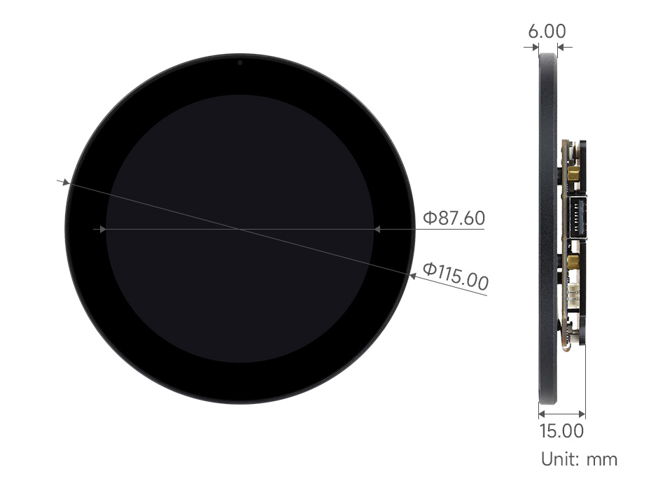
| Dimensiones del contorno | 115.00 × 115.00 (mm) | 126.00 × 126.00 (mm) |
| Área de visualización | 87.60 × 87.60 (mm) | 101.52 × 101.52 (mm) |
| Paso de píxeles | 0.12075 × 0.12075 (mm) | 0.1175 × 0.1088 (mm) |
| Temperatura de funcionamiento | 0℃ ~ 60℃ | |
2.3. Dimensiones del contorno

3. Características
- MCU de alto rendimiento: RISC-V 32-bit dual-core and single-core processors for demanding applications.
- Rich Multimedia Capabilities: Powerful image and voice processing with JPEG Codec, Pixel Processing Accelerator, Image Signal Processor, and H264 encoder.
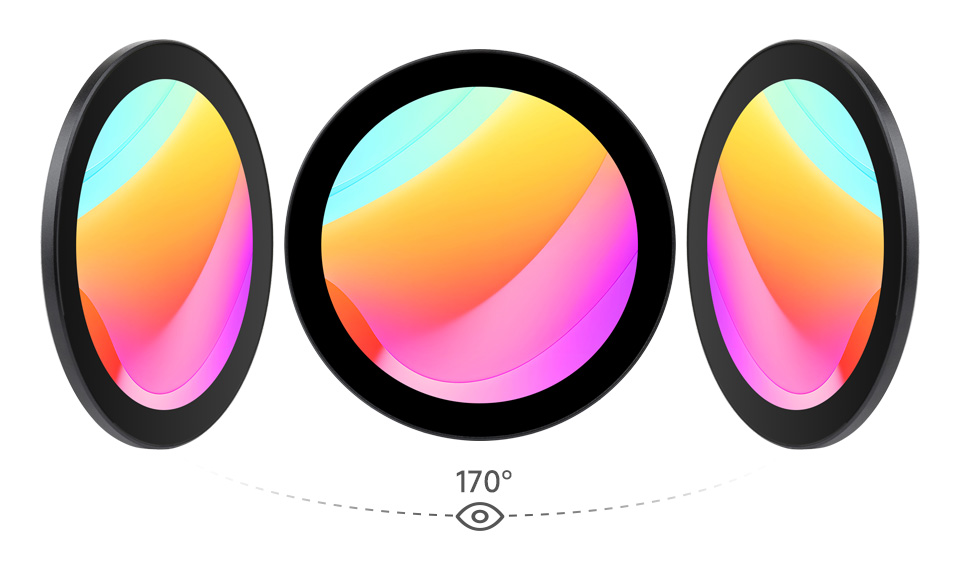
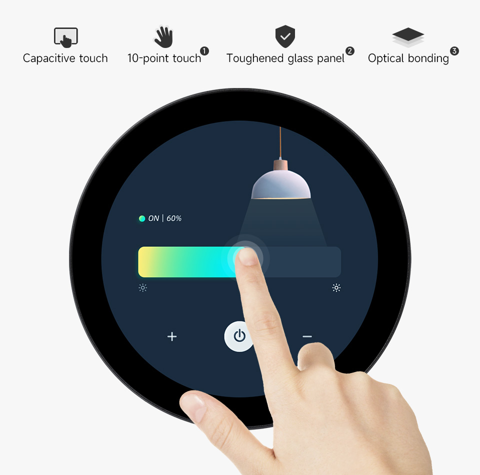
- Pantalla avanzada: IPS round touch display with 170° wide viewing angle, high contrast, and capacitive 10-point touch. Features a 6H hardness toughened glass panel and optical bonding for durability and clarity.
- Integrated Wireless Connectivity: Onboard ESP32-C6-MINI module provides 2.4GHz Wi-Fi 6 and Bluetooth 5 (LE) for stable and efficient wireless communication.
- Soporte completo de audio: ES8311 audio codec chip, ES7210 echo cancellation chip, dual microphones, and a speaker header enable robust audio input and output.
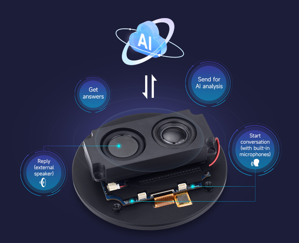
- Interacción de voz con IA: Supports mainstream AI platforms and can connect to large online models for advanced voice interaction capabilities.
- Periféricos extensos: Includes MIPI-CSI, MIPI-DSI, USB 2.0 OTG HS, SDIO 3.0 TF card slot, and a 40PIN GPIO header compatible with Raspberry Pi HATs for broad application adaptability.
- Seguridad robusta: Features Secure Boot, Flash Encryption, cryptographic accelerators, TRNG, Access Permission Management, and Privilege Separation for secure data and operations.
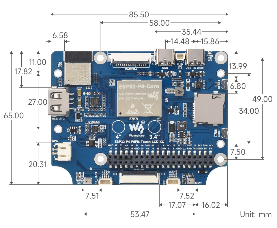
4. Componentes sobreview
The ESP32-P4 HMI DSI LCD Module is equipped with various components for its extensive functionality. Refer to the diagram below for a visual representation and the corresponding list for detailed descriptions.
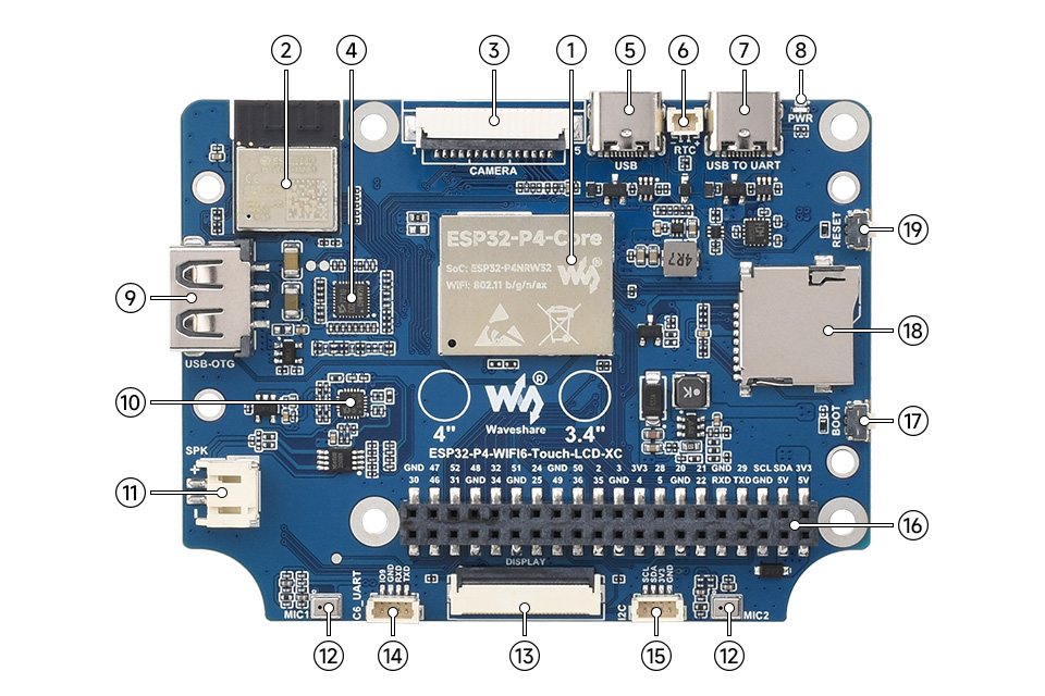
- ESP32-P4-Core: Integrated ESP32-P4NRW32, 32MB Nor Flash.
- ESP32-C6-MINI-1 module: SDIO interface protocol, extending Wi-Fi 6 / Bluetooth 5 (LE).
- MIPI CSI interface: 15Pin pitch 1.0mm connector, for connecting MIPI 2-lane camera.
- ES7210 echo cancellation chip: Used to eliminate echo and improve audio capture accuracy.
- Conector tipo C: USB 2.0 Full Speed interface, for power supply, program burning, and debugging.
- RTC battery header: For connecting rechargeable RTC battery (supports rechargeable RTC batteries only).
- USB TO UART Type-C connector: For power supply, program burning and debugging.
- Indicador LED de encendido: Indica el estado de energía.
- USB OTG Type-A connector: USB OTG 2.0 High-Speed interface.
- ES8311 low-power audio codec chip: For audio encoding and decoding.
- Speaker header: PH 2.0 2P connector, supports 8Ω 2W speaker (recommended).
- Onboard microphones: Microphone inputs with echo cancellation.
- MIPI DSI LCD interface: For connecting MIPI 2-lane LCD screen.
- ESP32-C6 UART header: SH1.0 4Pin connector, for ESP32-C6 module firmware burning.
- ESP32-P4 I2C header: SH1.0 4Pin connector, for connecting external I2C device.
- 40PIN GPIO header: Pitch 2.54mm, compatible with some Raspberry Pi HATs (a pinheader adapter is required).
- BOOT button: Press it when powering on or resetting to enter download mode.
- Ranura para tarjeta TF: SDIO 3.0 interface protocol.
- Botón de reinicio: Resets the module.
5. Instrucciones de configuración
Follow these steps to set up your ESP32-P4 HMI DSI LCD Module:
- Desembalaje: Carefully remove the module and any accessories from its packaging. Inspect for any visible damage.
- Conexión de energía: Connect a 5V power supply to the Type-C connector (5) or USB TO UART Type-C connector (7). Ensure the power source is stable and provides sufficient current.
- Conexión de pantalla: The display is typically pre-connected. If not, carefully connect the MIPI DSI LCD interface (13) to the display panel.
- Periféricos opcionales:
- Oradores: Connect an 8Ω 2W speaker to the Speaker header (11).
- Micrófonos: The module has onboard microphones (12).
- Tarjeta TF: Insert a formatted TF card into the TF card slot (18) if your application requires external storage.
- Cámara: Connect a compatible MIPI 2-lane camera to the MIPI CSI interface (3).
- External I2C Devices: Use the ESP32-P4 I2C header (15) to connect external I2C devices.
- GPIO Extensions: Utilize the 40PIN GPIO header (16) for connecting compatible Raspberry Pi HATs or other custom peripherals.
- Programming/Debugging Setup: For initial programming or debugging, connect the USB TO UART Type-C connector (7) to your computer. Install necessary drivers and development environment (e.g., ESP-IDF).
- Arranque inicial: After connecting power, the Power LED indicator (8) should light up. If you need to flash new firmware, press and hold the BOOT button (17) while powering on or resetting the module.
6. Instrucciones de funcionamiento
Once the module is set up, you can begin operation:
- Encendido: Ensure all connections are secure, then apply power. The display should initialize and show the programmed interface.
- Interacción táctil: Use the capacitive touch screen for intuitive control. The 10-point touch support allows for multi-finger gestures, depending on the software application.
- WiFi y Bluetooth: Configure Wi-Fi 6 and Bluetooth 5 (LE) connectivity through your application's software interface. This enables network access and communication with other Bluetooth devices.
- Interacción de voz con IA: If your application utilizes AI voice features, activate them through the software. The onboard microphones will capture voice commands, and the module can process them or send them to online AI platforms for analysis and response.
- Reproducción de audio: If speakers are connected, the module can play audio through the ES8311 audio codec.
- Funcionalidad de la cámara: If a camera is connected, your application can utilize its input for image processing or video streaming.
7. Mantenimiento
Para garantizar la longevidad y el rendimiento óptimo de su módulo:
- Limpieza: Gently clean the display surface with a soft, lint-free cloth. For stubborn smudges, use a screen-safe cleaning solution. Avoid abrasive materials or harsh chemicals.
- Manejo: Handle the development board by its edges to avoid touching sensitive components. Static electricity can damage electronic components, so use anti-static precautions when working with the bare board.
- Ambiente: Operate the module within the specified temperature range of 0℃ to 60℃. Avoid exposure to extreme temperatures, humidity, or direct sunlight.
- Actualizaciones de firmware: Regularly check for firmware updates from the manufacturer or community. Updates can improve performance, add features, or fix bugs. Follow the provided instructions carefully when performing updates.
- Almacenamiento: When not in use for extended periods, store the module in an anti-static bag in a cool, dry place.
8. Solución de problemas
If you encounter issues with your ESP32-P4 HMI DSI LCD Module, consider the following:
- Sin energía/pantalla:
- Check the power supply connection and ensure it provides stable 5V.
- Verify the power LED indicator (8) is lit.
- Ensure the display cable is securely connected to the MIPI DSI LCD interface (13).
- La pantalla táctil no responde:
- Ensure the display is properly connected and initialized.
- Verifique si hay obstrucciones físicas o daños en la superficie táctil.
- A software issue might be preventing touch input; try resetting the module using the RESET button (19).
- Problemas de conectividad Wi-Fi/Bluetooth:
- Verify that the ESP32-C6-MINI-1 module (2) is functioning correctly.
- Check your application's code for correct Wi-Fi/Bluetooth initialization and configuration.
- Ensure you are within range of your Wi-Fi network or Bluetooth device.
- Error en la carga del firmware:
- Ensure the USB TO UART Type-C connector (7) is properly connected to your computer.
- Press and hold the BOOT button (17) while resetting or powering on the module to enter download mode before attempting to flash firmware.
- Verifique que los controladores correctos estén instalados en su computadora.
- Problemas de audio:
- Check speaker connections to the Speaker header (11).
- Ensure the ES8311 audio codec chip (10) and ES7210 echo cancellation chip (4) are correctly initialized by your software.
- Verify microphone settings in your application.
- Inestabilidad general: Try pressing the RESET button (19) to restart the module. If issues persist, re-flash the firmware.
9. Consejos para el usuario
Si bien no hay ningún usuario específicoviews or Q&A were provided, here are some general tips for working with development boards like the ESP32-P4 HMI DSI LCD Module:
- Empezar con Exampellos: Begin by running official example code or community-contributed projects to familiarize yourself with the module's capabilities and development environment.
- Leverage the Community: ESP32 platforms have active online communities. Forums and documentation can be invaluable resources for troubleshooting, finding code examples, and learning best practices.
- Modular Development: When building complex projects, develop and test features incrementally. This makes debugging easier and helps isolate issues.
- Administración de energía: Pay attention to power consumption, especially for battery-powered applications. Optimize your code and hardware configuration for efficiency.
- GPIO Management: Be mindful of GPIO pin assignments to avoid conflicts, especially when using the 40PIN GPIO header with multiple peripherals. Refer to the pinout diagrams and documentation.
- Integración de IA: For AI voice interaction, experiment with different AI models and platforms to find the best fit for your application's needs and performance requirements.
10. Garantía y soporte
For warranty information, technical support, or service inquiries, please contact SURENOO Official Store directly through their official channels. Ensure you have your product model number (SU8080P434C or SU7272P440C) and purchase details available when seeking support.


