1. Introducción
This manual provides essential information for the safe and effective installation, operation, and maintenance of your Vimar 14015 Serie Plana 2-Pole White Switch. This product is a 2-pole switch designed for electrical circuits, rated at 16 Amperes and 250 Volts. It features an illuminable and replaceable push button, making it suitable for various residential and commercial applications.
2. Información de seguridad
Lea atentamente todas las instrucciones de seguridad antes de instalar y usar el producto. El incumplimiento de estas instrucciones podría provocar una descarga eléctrica, un incendio o lesiones graves.
- Desconectar la energía: Always ensure the main power supply to the circuit is turned off at the circuit breaker or fuse box before attempting any installation, wiring, or maintenance.
- Electricista calificado: Installation should only be performed by a qualified electrician or competent person in accordance with all local and national electrical codes and regulations.
- Volumentage y actual: No exceda el volumen especificadotage (250V) and current (16A) ratings of the switch.
- Clasificación IP40: This switch has an International Protection Rating of IP40, meaning it is protected against solid objects larger than 1mm but offers no protection against liquids. Do not install in areas where it may be exposed to water or high humidity.
- Material: The switch is constructed from metal. Ensure proper grounding if required by local codes.
3. Contenido del paquete
- 1 x Vimar 14015 Serie Plana 2-Pole White Switch
4. Instalación
Follow these steps for proper installation of the Vimar 14015 switch.
4.1 Preinstalación
- Apague la energía: Locate the circuit breaker or fuse controlling the area where the switch will be installed and turn off the power. Verify power is off using a voltage probador.
- Preparar el cableado: Ensure the existing wiring is suitable for a 2-pole, 16A, 250V switch.
4.2 Cableado
The Vimar 14015 switch is designed for 2-way circuits and features quick connect terminals. Refer to the diagram below for terminal identification.
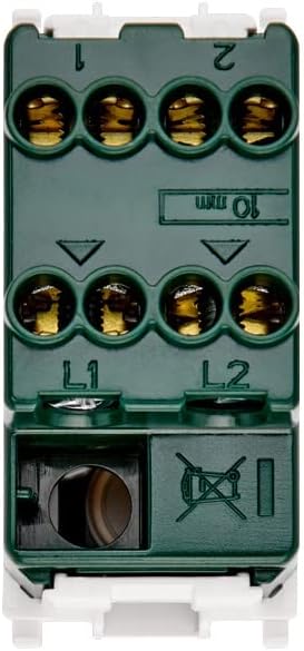
Figura 1: Atrás view of the Vimar 14015 switch with wiring terminals. Terminals L1 and L2 are for incoming power lines, and terminals 1 and 2 are for outgoing load connections in a 2-way circuit.
- Connect the incoming live wires to terminals labeled L1 y L2.
- Connect the outgoing load wires to terminals labeled 1 y 2.
- Ensure all connections are secure and wires are fully inserted into the quick connect terminals.
4.3 Montaje
This switch is designed for surface mount installation.

Figura 2: Lado view of the Vimar 14015 switch, indicating its compact design and model identification.
- Carefully place the switch into the appropriate mounting box or frame.
- Secure the switch using the provided screws or clips, ensuring it is flush and stable.
4.4 Post-instalación
- Restaurar energía: Una vez completada la instalación y todas las conexiones estén seguras, restablezca la energía en el disyuntor.
- Funcionalidad de prueba: Press the switch button to verify proper ON-OFF operation and check if the illumination functions correctly.
5. Instrucciones de funcionamiento
The Vimar 14015 switch operates with a simple push-button mechanism.

Figura 3: Frente view of the Vimar 14015 switch, showing the push-button actuator.
- Función de encendido/apagado: Press the upper part of the button to turn the connected device or light ON. Press the lower part of the button to turn it OFF.
- Iluminación: If the switch is configured for illumination, a light indicator will be visible on the button when the switch is in a specific state (e.g., ON or OFF, depending on wiring).
- Replaceable Button: The button is designed to be replaceable. If replacement is needed, ensure power is disconnected before attempting to remove or install a new button.
6. Mantenimiento
The Vimar 14015 switch requires minimal maintenance.
- Limpieza: To clean the switch, wipe it with a soft, dry cloth. Do not use abrasive cleaners, solvents, or excessive moisture, as this can damage the finish or internal components.
- No hay piezas que el usuario pueda reparar: There are no user-serviceable parts inside the switch other than the replaceable button. Do not attempt to disassemble the switch.
7. Solución de problemas
If you encounter issues with your Vimar 14015 switch, refer to the following common problems and solutions.
- Switch Not Working:
- Ensure the main power supply to the circuit is ON.
- Verify that all wiring connections (L1, L2, 1, 2) are secure and correctly installed.
- Check the connected load (e.g., light bulb) to ensure it is functional.
- La iluminación no funciona:
- Confirm that the switch is correctly wired for illumination.
- If the illumination is provided by a separate component (e.g., an LED module), ensure it is correctly installed and functional.
If problems persist after attempting these troubleshooting steps, contact a qualified electrician or Vimar customer support.
8. Especificaciones
| Especificación | Valor |
|---|---|
| Marca | Vimar |
| Número de modelo | SERIE PLANA (14015) |
| Modo de operación | ENCENDIDO APAGADO |
| Calificación actual | 16 Amps |
| Vol de funcionamientotage | 250 voltios |
| Tipo de contacto | Normalmente abierto |
| Tipo de conector | Conexión rápida |
| Tipo de circuito | 2 vías |
| Tipo de actuador | Botón pulsador |
| Calificación de protección internacional | IP40 |
| Número de posiciones | 2 |
| Método de control | Tocar |
| Color | Blanco |
| Quétage | 200 vatios |
| Material | Metal |
| Tipo de montaje | Montaje en superficie |
| Dimensiones del producto (L x An x Al) | 0.88 x 1.51 x 1.92 pulgadas |
| Peso del artículo | 1.06 onzas |
9. Garantía y soporte
Vimar products are manufactured to high-quality standards. For specific warranty information, please refer to the documentation provided with your purchase or visit the official Vimar website. For technical support or assistance, please contact Vimar customer service through their official channels.


