1. Introducción
This manual provides comprehensive instructions for the installation, configuration, operation, and maintenance of the Planet IGS-10020HPT Industrial 8-Port 10/100/1000T 802.3at PoE + 2-Port 100/1000X SFP Managed Switch. Please read this manual thoroughly before operating the device to ensure proper usage and to prevent damage.
1.1 producto másview
The Planet IGS-10020HPT is a robust industrial-grade managed Ethernet switch designed for demanding environments. It features 8 Gigabit Ethernet ports with Power over Ethernet Plus (PoE+) capabilities and 2 Gigabit SFP ports for fiber optic connections. This switch supports advanced management functions and operates reliably across a wide temperature range.
1.2 Características principales
- 8 x 10/100/1000BASE-T Gigabit Ethernet ports with 802.3at PoE+ capability
- 2 x 100/1000BASE-X SFP slots for fiber optic uplink
- Supports IEEE 1588v2 Transparency for precise time synchronization
- ERPS Ring support for network redundancy
- DIDO (Digital Input/Digital Output) for external device monitoring and control
- Integrated Cybersecurity Features for enhanced network security
- Wide operating temperature range: -40 to 75°C (-40 to 167°F)
- Dual 12~48V DC power input with 52V Power Boost for PoE
- Managed switch capabilities for advanced network control
- e-Mark Certified for vehicle applications
2. Contenido del paquete
Please verify the contents of your package. If any items are missing or damaged, contact your vendor immediately.
- Planet IGS-10020HPT Industrial Managed PoE+ Switch
- Guía de instalación rápida (si está incluida)
- Mounting Kit (DIN-rail or wall-mount brackets)
- Terminal Block Connector for Power Input and DIDO
3. Descripción física
3.1 Disposición del panel frontal
The front panel of the IGS-10020HPT features the Ethernet ports, SFP slots, console port, and LED indicators.

Figura 3.1: Delante y lateral view of the Planet IGS-10020HPT Industrial Managed PoE+ Switch. This image shows the device from an angled perspective, highlighting the 8 PoE+ Gigabit Ethernet ports, 2 SFP slots, console port, and LED indicators on the front panel. The ribbed metal casing for heat dissipation is also visible.
- Puerto de consola: RJ45 port for local management access.
- Puertos PoE (1-8): 10/100/1000BASE-T ports with 802.3at PoE+ capability.
- Puertos SFP (9-10): 100/1000BASE-X SFP slots for fiber optic transceivers.
- Indicadores LED: Power (P1, P2), Fault, Ring, PoE status, Link/Act for each port.
- Botón de reinicio: For resetting the device to factory defaults.
3.2 Top Panel Layout
The top panel provides connections for power input and digital input/output.

Figura 3.2: Arriba view of the Planet IGS-10020HPT. This image displays the two green terminal block connectors on the top surface. The top connector is labeled for "2 Digital Input" and "2 Digital Output" (DI0, DI1, DO0, DO1, GND, GND). The bottom connector is for dual DC power input (DC1, Fault, Input DC 48V, DC2).
- Power Input (DC1, DC2): Dual redundant DC power inputs (12~48V DC).
- Fault Relay: Output for alarm signaling.
- Digital Input (DI0, DI1): For connecting external sensors or switches.
- Digital Output (DO0, DO1): For controlling external devices or alarms.
3.3 Side Panel with Mounting Brackets
The side panels are designed for heat dissipation and feature mounting points for DIN-rail or wall-mount brackets.
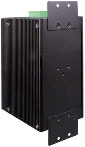
Figura 3.3: Lado view of the Planet IGS-10020HPT. This image shows the ribbed metal casing and the attached L-shaped mounting brackets, indicating options for installation.
4. Instalación
4.1 Precauciones de seguridad
- Ensure the power is disconnected before installation or maintenance.
- Instale el dispositivo en un área bien ventilada.
- Avoid exposing the device to moisture or extreme temperatures outside its operating range.
- Ground the device properly to prevent electrical hazards.
4.2 Montaje del interruptor
The IGS-10020HPT can be mounted on a DIN-rail or directly to a wall using the provided brackets.
4.2.1 Montaje en riel DIN
- Attach the DIN-rail clip to the rear of the switch using the screws.
- Hook the top edge of the DIN-rail clip over the top of the DIN-rail.
- Push the bottom of the switch towards the DIN-rail until it snaps into place.
4.2.2 Montaje en pared
- Attach the wall-mount brackets to the sides of the switch using the screws.
- Mark the desired mounting points on the wall using the brackets as a template.
- Perfore agujeros piloto e inserte anclajes de pared adecuados si es necesario.
- Secure the switch to the wall using screws through the bracket holes.
4.3 Conexión de alimentación
Connect the power source to the terminal block connector on the top panel.
- Ensure the power source is within the specified range (12~48V DC).
- Connect the positive (+) and negative (-) wires from your DC power supply to the corresponding terminals (DC1 or DC2) on the terminal block.
- For redundant power, connect a second power supply to the other DC input.
- Apriete firmemente los tornillos del bloque de terminales.
4.4 Conexión de red
4.4.1 puertos Ethernet
Connect standard RJ45 Ethernet cables from your network devices (e.g., IP cameras, access points, computers) to the 10/100/1000BASE-T ports (1-8) on the front panel. These ports will automatically detect the speed and duplex mode of the connected device. PoE-enabled devices will receive power automatically.
4.4.2 puertos SFP
Insert compatible 100BASE-FX or 1000BASE-X SFP transceivers into the SFP slots (9-10). Connect fiber optic cables from your fiber network to the installed SFP transceivers.
5. Funcionamiento del interruptor
5.1 Encendido
After connecting the power supply, the switch will power on automatically. Observe the P1 and P2 LEDs on the front panel. They should illuminate to indicate active power input.
5.2 Indicadores LED
Monitoree los indicadores LED en el panel frontal para comprender el estado del interruptor:
- P1/P2 (Potencia): On when power input 1/2 is active.
- CULPA: On when a system fault is detected.
- ANILLO: Indicates the status of the ERPS ring.
- PoE (per port): On when PoE power is being supplied to the connected device.
- Link/Act (per port): On when a valid network link is established, blinks during data activity.
5.3 Acceso a la administración
The IGS-10020HPT is a managed switch, offering various methods for configuration and monitoring:
- WebGestión basada en: Acceda al conmutador web interfaz a través de un estándar web navegador introduciendo su dirección IP.
- Puerto de consola: Connect a console cable from your computer to the RJ45 console port for command-line interface (CLI) access.
- Sistema operativo: The switch supports SNMP for network management system integration.
Refer to the full software user manual (available on the Planet Technology website) for detailed instructions on configuring advanced features such as VLANs, QoS, security settings, and ERPS ring management.
6. Mantenimiento
6.1 Limpieza
Limpie periódicamente el exterior del interruptor con un paño suave y seco. No utilice limpiadores líquidos ni en aerosol. Asegúrese de que las aberturas de ventilación estén libres de polvo y residuos.
6.2 actualizaciones de firmware
Check the Planet Technology website regularly for firmware updates. Keeping the firmware up-to-date ensures optimal performance, security, and access to new features. Follow the instructions provided with the firmware update package carefully.
6.3 Restablecimiento a valores predeterminados de fábrica
To reset the switch to its factory default settings, press and hold the Reset button on the front panel for approximately 5-10 seconds until the LEDs indicate a reset sequence. Use this function with caution as it will erase all custom configurations.
7. Solución de problemas
Esta sección proporciona soluciones a problemas comunes que puede encontrar.
| Problema | Posible causa | Solución |
|---|---|---|
| El interruptor no se enciende. | No power input; faulty power supply; incorrect wiring. | Verify power connections and power supply functionality. Check P1/P2 LEDs. |
| No link on an Ethernet port. | Faulty cable; incorrect cable type; connected device is off or faulty. | Check cable integrity; ensure connected device is powered on and functioning. Try a different port or cable. |
| El dispositivo PoE no recibe energía. | Device not 802.3af/at compliant; cable too long; power budget exceeded. | Verify device PoE compatibility; check cable length; ensure total PoE power consumption does not exceed switch capacity. Check PoE LED for the port. |
| No se puede acceder web Interfaz de gestión. | Incorrect IP address; network configuration issue; firewall blocking access. | Verify the switch's IP address and your computer's network settings. Try connecting via the console port. |
If the problem persists after attempting these solutions, please contact Planet Technology technical support.
8. Especificaciones
| Característica | Descripción |
|---|---|
| Modelo | IGS-10020HPT |
| Puertos | 8 x 10/100/1000BASE-T (PoE+), 2 x 100/1000BASE-X SFP |
| PoE estándar | IEEE 802.3af/at Power over Ethernet Plus |
| Max Watts/Port | 30W (depends on power input) |
| Velocidad de transferencia de datos | 10/100/1000 Mbps |
| Entrada de potencia | Dual 12~48V DC (52V Power Boost for PoE) |
| Temperatura de funcionamiento | -40 a 75 °C (-40 a 167 °F) |
| Material de la caja | Metal |
| Dimensiones (LxAnxAl) | 5.98 x 4.21 x 2.83 pulgadas (15.19 x 10.69 x 7.19 cm) |
| Peso del artículo | 2.42 libras (1096 gramos) |
| Certificaciones | e-Mark Certified (among others) |
| Características | IEEE 1588v2 Transparency, ERPS Ring, DIDO, Cybersecurity Features |
9. Garantía y soporte
Planet Technology products are backed by a manufacturer's warranty. For specific warranty terms and conditions, please refer to the warranty card included with your product or visit the official Planet Technology websitio.
For technical support, product documentation, or firmware updates, please visit the Planet Technology official website or contact their customer service department. When contacting support, please have your product model number (IGS-10020HPT) and serial number ready.
Oficial Websitio: www.planeta.com.tw


