1. Introducción
This manual provides essential instructions for the safe and effective operation of the Mustool MT866 Digital True RMS Clamp Meter. The MT866 is a versatile instrument designed for measuring AC/DC voltage, AC/DC current, frequency, temperature, capacitance, resistance, and continuity. It also features a live wire check function and non-contact voltage detection for enhanced safety. Please read this manual thoroughly before using the device.
2. Información de seguridad
Siga siempre las siguientes precauciones de seguridad para evitar lesiones personales o daños al medidor:
- No exceda los límites máximos de entrada for any measurement function.
- Tenga mucho cuidado al trabajar con circuitos activos. Alto volumentagPuede ser peligroso.
- Ensure the test leads are in good condition, without any damage to the insulation.
- Do not operate the meter if it appears damaged or if the battery cover is not properly closed.
- Always disconnect the test leads from the circuit before changing the function dial.
- Use the correct function and range para cada medida.
- Mantenga los dedos detrás de los protectores de dedos. en las sondas de prueba durante las mediciones.
- Avoid using the meter in wet environments or in the presence of explosive gases or dust.
- The meter is rated for CAT III 600V and CAT II 600V. Do not use it for measurements exceeding these categories.
3. Producto terminadoview
The Mustool MT866 is a compact and feature-rich clamp meter. Familiarize yourself with its components:
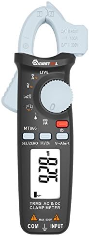
Figura 1: Frente View of the Mustool MT866 Clamp Metro. This image displays the main components including the clamp jaw, LCD display, function dial, and control buttons.
3.1. Componentes
- Clamp Mandíbula: Se utiliza para medir corriente CA/CC sin contacto.
- Clamp Palanca de liberación: Abre el clamp mandíbula.
- Vol sin contactotage (NCV) Sensor: Detecta el volumen de CAtagy sin contacto directo.
- Pantalla LCD: Muestra lecturas de medición, unidades e indicadores de función.
- Dial de función: Selects the desired measurement mode.
- SEL/ZERO Button: Selects sub-functions or zeros the DC current reading.
- H/💡 Button: Activates Data Hold or backlight.
- V~Alert Button: Activates the V~ alert function for live wire detection.
- Terminales de entrada (COM, INPUT): Para conectar cables de prueba para vol.tage, mediciones de resistencia, capacitancia, frecuencia y temperatura.
- Back Hook: For convenient hanging of the meter.
3.2. Indicadores de visualización
- AC/DC: Indicates Alternating Current or Direct Current.
- V: Voltios (Voltagmi).
- A: Amperes (Actual).
- Ω: Ohmios (Resistencia).
- F: Farads (Capacitance).
- Hz: Hertz (Frequency).
- ° C / ° F: Degrees Celsius/Fahrenheit (Temperature).
- VIVIR: Live wire detection indicator.
- LOZ: vol de baja impedanciatage modo de medición.
- H: Data Hold activated.
- Símbolo de batería: Indicador de batería baja.
4. Configuración
4.1. Instalación de la batería
The Mustool MT866 requires batteries for operation (not included in the package). To install or replace batteries:
- Asegúrese de que el medidor esté apagado y todos los cables de prueba estén desconectados.
- Localice la tapa del compartimiento de la batería en la parte posterior del medidor.
- Desatornille el/los tornillo(s) de retención y retire la cubierta.
- Inserte pilas nuevas, respetando la polaridad correcta (+ y -).
- Vuelva a colocar la tapa de la batería y fíjela con el/los tornillo(s).
4.2. Conexión de los cables de prueba
Para la mayoría de las mediciones (voltage, resistance, capacitance, etc.), test leads are required.

Figure 2: Mustool MT866 with Test Leads. The black test lead is connected to the COM terminal, and the red test lead is connected to the INPUT terminal.
- Conectar el cable de prueba negro hacia COM Terminal de entrada (común).
- Conectar el cable de prueba rojo hacia APORTE Terminal.
- Asegúrese de que las conexiones estén firmes antes de tomar cualquier medición.
5. Instrucciones de funcionamiento
Turn the function dial to the desired measurement mode. Use the SEL/ZERO button to switch between sub-functions (e.g., AC/DC, Resistance/Continuity/Diode).
5.1. Vol. CA / CCtagy Medición (V)
- Gire el dial de función a la V posición.
- Utilice el SEL/ZERO button to select AC (V~) or DC (V=) voltage.
- Conecte los cables de prueba en paralelo al circuito o componente bajo prueba.
- Leer el vol.tage valor en la pantalla.
5.2. Low Impedance VoltagMedición e (LOZ)
- Gire el dial de función a la LOZ posición.
- This mode automatically detects AC or DC voltage with a low input impedance, which can help drain ghost voltages and provide more accurate readings in certain applications.
- Conecte los cables de prueba en paralelo al circuito.
5.3. AC/DC Current Measurement (A) - Clamp
- Gire el dial de función a la A posición.
- Utilice el SEL/ZERO button to select AC (A~) or DC (A=) current.
- Presione la tecla clamp palanca de liberación para abrir el clamp mandíbula.
- Encierre sólo un conductor del circuito dentro del clamp mandíbula.
- Para corriente continua, presione SEL/ZERO to zero the reading before measurement if necessary.
- Lea el valor actual en la pantalla.
5.4. Resistance (Ω), Continuity, Diode Test
- Gire el dial de función a la Ω posición.
- Utilice el SEL/ZERO button to cycle between Resistance, Continuity, and Diode Test modes.
- Resistencia: Connect test leads across the component. Ensure the circuit is de-energized.
- Continuidad: If resistance is below approximately 30Ω, the buzzer will sound.
- Prueba de diodo: Connect the red lead to the anode and black lead to the cathode. The display shows the forward voltagCaída electrónica. Invierta los cables para comprobar si hay circuito abierto.
5.5. Capacitance (µF) Measurement
- Gire el dial de función a la microfaradios posición.
- Discharge the capacitor completely before connecting the test leads.
- Conecte los cables de prueba a los terminales del capacitor.
- Lea el valor de capacitancia en la pantalla.
5.6. Medición de frecuencia (Hz)
- Frequency can be measured from the jaw (when in AC current mode) or from the input terminals (when in AC voltagmodo electrónico).
- When in ACV or ACA mode, press the SEL/ZERO button to cycle to the frequency measurement.
- Conecte los cables de prueba o clamp the conductor as appropriate for the primary measurement.
5.7. Temperature (°C/°F) Measurement

Figure 3: Mustool MT866 with Temperature Probe. The temperature probe is connected to the input terminals for temperature measurements.
- Gire el dial de función a la TEMPERATURA posición.
- Connect the temperature test probe to the input terminals (red to INPUT, black to COM).
- Coloque la punta de la sonda de temperatura sobre o cerca del objeto cuya temperatura se va a medir.
- Read the temperature on the display. Use SEL/ZERO para cambiar entre Celsius y Fahrenheit.
5.8. Live Wire Check (LIVE)
- Gire el dial de función a la VIVIR posición.
- Insert the red test lead into the live wire socket. The display will show "LIVE" and an alarm will sound if a live wire is detected.
5.9. Vol sin contactotage (V~Alert) Detection
- Presione el V ~ Alerta Botón para activar el modo NCV.
- Move the top of the meter (where the NCV sensor is located) close to a conductor or outlet.
- Si AC voltage is detected, the meter will beep and the LED indicator will flash, with the intensity increasing como el voltagLa fuerza aumenta.
5.10. µA HVAC Flame Rod Test
- Gire el dial de función a la mA posición.
- This function is specifically designed for measuring microamperes in HVAC flame rod applications (0-200.0µA).
- Connect the test leads in series with the flame rod circuit.
5.11. Data Hold (H) and Backlight (💡)
- Presione el H/💡 button briefly to activate Data Hold, freezing the current reading on the display. Press again to release.
- Mantenga pulsado el H/💡 botón para encender o apagar la retroiluminación.
6. Mantenimiento
6.1. Limpieza
- Limpie el medidor con publicidadamp paño y detergente suave. No utilice abrasivos ni disolventes.
- Asegúrese de que el medidor esté completamente seco antes de usarlo.
6.2. Reemplazo de la batería
When the battery symbol appears on the display, replace the batteries as described in Section 4.1. Prompt battery replacement ensures accurate readings and proper device function.
6.3. Almacenamiento
- Si el medidor no se utiliza durante un período prolongado, retire las baterías para evitar fugas.
- Guarde el medidor en un lugar fresco y seco, alejado de la luz solar directa y de temperaturas extremas.
7. Solución de problemas
| Problema | Posible causa | Solución |
|---|---|---|
| Sin pantalla o pantalla tenue | Baterías bajas o agotadas; instalación incorrecta de la batería. | Reemplace las baterías; verifique la polaridad de las baterías. |
| Se muestra "OL" o "OVER" | La medición excede el rango seleccionado. | Select a higher range or check if the input is too high for the meter. |
| Lecturas inexactas | Poor test lead connection; incorrect function/range selected; external interference. | Ensure firm connections; select appropriate function/range; move away from strong electromagnetic fields. |
| No hay pitido de continuidad | Circuit resistance too high; continuity mode not selected. | Ensure resistance is below 30Ω; press SEL/ZERO to select continuity mode. |
8. Especificaciones
The following are the general specifications for the Mustool MT866 Digital True RMS Clamp Metro:
- Pantalla máx.: 6000 cuentas
- AC Current (ACA): 6A/60A/100A (±2.5%+5)
- Corriente continua (DCA): 6A/60A/100A (±2.5%+5)
- Vol. CAtage (VSM): 6V/60V/600V (±1%+3)
- Vol DCtagy (DCV): 6V/60V/600V (±1%+3)
- Volumen de baja impedanciatage (LoZ ACV-DCV Auto Scan): 600.0V / 300kΩ input impedance
- Resistencia (OHM): 600Ω/6KΩ/60KΩ/600KΩ/6MΩ/60MΩ (±1%+3)
- Capacidad: 600.0µF/6000µF (±4%+3)
- Frecuencia (Hz): 60Hz/1000Hz (from jaw or input terminals)
- Temperatura: -20 ~ 500 ° C / -4 ~ 932 ° F
- µA HVAC Flame Rod Test: 0~200.0μA
- Zumbador de continuidad: Menos de 30Ω
- Estilo: Digital
- Tipo de medida: Multímetro
- Clasificación de seguridad: CAT III 600 V, CAT II 600 V
9. Contenido del paquete
The Mustool MT866 package typically includes the following items:
- 1 x Mustool MT866 Digital True RMS Clamp Meter (Batteries are not included)
- 1 x Pair Test Probe (Red and Black)
- 1 x 1M (Length) Temperature Test Probe
- 1 x Manual de usuario en inglés (este documento)
10. Garantía y soporte
Para obtener información sobre la garantía, asistencia técnica o consultas de servicio, consulte la documentación proporcionada al momento de la compra o comuníquese con su distribuidor. Conserve el recibo de compra como comprobante.