1. Introducción
This manual provides essential information for the installation, operation, maintenance, and troubleshooting of the Juniper Networks EX4200-24P 24-Port Power over Ethernet (PoE) Ethernet Switch. The EX4200-24P is designed to provide high-performance, reliable network connectivity for enterprise and data center environments, offering 24 Gigabit Ethernet ports with PoE+ capabilities and Layer 3 features.
2. Información de seguridad
Tenga en cuenta las siguientes precauciones de seguridad para evitar lesiones y daños al equipo:
- Asegúrese de que el dispositivo esté correctamente conectado a tierra.
- No opere el interruptor en entornos mojados o excesivamente húmedos.
- Desconecte la alimentación antes de realizar cualquier procedimiento de mantenimiento o instalación.
- Utilice únicamente cables de alimentación y accesorios aprobados.
- Ensure adequate ventilation around the switch to prevent overheating.
3. Contenido del paquete
Verifique que su paquete contenga los siguientes elementos:
- Juniper Networks EX4200-24P Ethernet Switch
- Cable de alimentación
- Rack-mount Kit (brackets, screws)
- Cable de consola (RJ-45 a DB-9)
- Documentación (Guía de inicio rápido, Información de seguridad)
Note: Contents may vary based on the specific renewed product offering.
4. Exceso de físicoview
4.1 Panel frontal
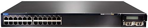
Figure 4.1: Front Panel of EX4200-24P Switch. This image displays the front of the Juniper Networks EX4200-24P switch, featuring 24 RJ-45 Gigabit Ethernet ports, each with LED indicators, and four SFP+ uplink ports on the right side, along with a small LCD display and control buttons.
The front panel of the EX4200-24P switch includes:
- 24 puertos Ethernet 10/100/1000BASE-T: RJ-45 connectors for network devices. Each port supports Power over Ethernet Plus (PoE+).
- LED de estado del puerto: Indicators for link status, activity, and PoE status for each port.
- Uplink Module Slot: Typically houses 4x SFP/SFP+ ports for high-speed uplinks to other network devices or the core network.
- Pantalla LCD: Provides system status, configuration information, and error messages.
- Botones de control: Used to navigate and interact with the LCD display menu.
- LED de estado del sistema: Indicators for power, alarm, and system status.
4.2 Panel trasero

Figura 4.2: Angulado View of EX4200-24P Switch. This image provides an angled perspective of the Juniper Networks EX4200-24P switch, highlighting the front panel with its 24 Ethernet ports and uplink module, and giving a partial view of the side chassis. The rear panel, not fully visible in this image, typically contains power input, fan modules, and a console port.
El panel trasero normalmente incluye:
- Conector de alimentación de CA: Para conectar el cable de alimentación.
- Console Port (RJ-45): For local management and initial configuration using a serial connection.
- Puerto USB: For software upgrades or configuration backup/restore.
- Módulos de ventilador: Removable fan trays for cooling.
5. Configuración e instalación
5.1 Preparación del sitio
Antes de la instalación, asegúrese de que el lugar de instalación cumpla con los siguientes requisitos:
- Ambiente: Maintain an ambient temperature between 0°C and 45°C (32°F and 113°F) and relative humidity between 10% and 85% (non-condensing).
- Fuerza: A dedicated power outlet with proper grounding is recommended.
- Ventilación: Ensure at least 5 cm (2 inches) of clearance at the front and rear for airflow.
5.2 Montaje en bastidor
The EX4200-24P is designed for installation in a standard 19-inch equipment rack.
- Fije los soportes de montaje en rack provistos a los lados del conmutador utilizando los tornillos suministrados.
- Alinee el interruptor con los postes del rack y fíjelo utilizando los tornillos de rack adecuados.
5.3 Conexión de alimentación
- Connect one end of the power cord to the AC power connector on the rear panel of the switch.
- Conecte el otro extremo del cable de alimentación a una toma eléctrica con conexión a tierra.
- The switch will power on automatically. Observe the system status LEDs for initial boot-up.
5.4 Conexiones de red
- Conecte los cables Ethernet de sus dispositivos de red (computadoras, teléfonos IP, puntos de acceso inalámbricos) a los puertos RJ-45 en el panel frontal.
- For uplink connections to other switches or routers, insert appropriate SFP/SFP+ transceivers into the uplink module slot and connect fiber or copper cables as required.
- For initial configuration, connect a console cable from your management workstation to the console port on the rear panel.
6. Funcionamiento del interruptor
6.1 Encendido y arranque inicial
Once connected to power, the switch will begin its boot sequence. The system status LEDs will indicate the boot progress. The LCD display will show system information during startup.
6.2 Indicadores LED
Monitor the LEDs on the front panel to understand the switch's operational status:
- LED del sistema: Indicates overall system health (e.g., green for normal operation, amber for minor alarm, red for major alarm).
- LED de encendido: Indica el estado de energía.
- Port Link/Activity LEDs:
- Verde sólido: Enlace establecido.
- Verde intermitente: Actividad en el puerto.
- Apagado: No hay enlace.
- LED de estado de PoE: Indicate Power over Ethernet status for PoE-enabled ports.
6.3 Acceso a la configuración básica
The switch can be configured via the command-line interface (CLI) through the console port or remotely via Telnet/SSH after initial IP configuration. Refer to the Juniper Networks documentation for detailed CLI commands and configuration guides.
- Puerto de consola: Use a terminal emulator (e.g., PuTTY) with settings: 9600 baud, 8 data bits, no parity, 1 stop bit, no flow control.
- Web Interfaz: Some Juniper switches offer a web-based management interface. Check your specific firmware version for availability and default access details.
7. Mantenimiento
7.1 Limpieza
Regular cleaning helps maintain optimal performance and extends the lifespan of the switch.
- Power off and disconnect the switch before cleaning.
- Utilice un paño suave y seco para limpiar el exterior.
- Use compressed air to clear dust from ventilation openings and fan modules.
- No utilice limpiadores líquidos o en aerosol directamente sobre el interruptor.
7.2 actualizaciones de firmware
Verifique periódicamente el soporte de Juniper Networks website for the latest firmware updates. Firmware updates can provide new features, performance improvements, and security patches. Follow the instructions provided with the firmware package for proper installation.
7.3 Consideraciones ambientales
Ensure the switch operates within its specified temperature and humidity ranges. Avoid blocking ventilation ports and ensure proper airflow to prevent overheating, which can lead to system instability or failure.
8. Solución de problemas
Esta sección proporciona soluciones a problemas comunes que puede encontrar.
8.1 Sin energía
- Verifique que el cable de alimentación esté conectado de forma segura tanto al interruptor como al tomacorriente.
- Compruebe si la toma de corriente funciona enchufando otro dispositivo.
- Ensure the power supply unit (if modular) is properly seated.
8.2 No hay enlace en el puerto
- Comprueba la conexión del cable Ethernet en ambos extremos. Prueba con otro cable.
- Verifique que el dispositivo conectado esté encendido y funcionando correctamente.
- Check the port configuration on the switch (e.g., speed, duplex settings).
8.3 Problemas de conectividad de red
- Confirm the switch has a valid IP address and network configuration.
- Compruebe si hay conflictos de direcciones IP en la red.
- Verify VLAN configurations if applicable.
- Reinicie el conmutador y los dispositivos conectados.
8.4 Restablecimiento de fábrica
A factory reset will erase all configurations and restore the switch to its default settings. Consult the Juniper Networks documentation for the specific procedure for the EX4200 series, as it typically involves a specific command sequence via the console port.
9. Especificaciones técnicas
| Característica | Especificación |
|---|---|
| Modelo | EX4200-24P |
| Marca | Redes Juniper |
| Número de puertos | 24 x 10/100/1000BASE-T (PoE+) |
| Tipo de interfaz | RJ45 |
| Dimensiones del producto (LxAnxAl) | 23 x 22.75 x 11 pulgadas (58.42 x 57.78 x 27.94 cm) |
| Peso del artículo | 23.1 libras (10.48 kg) |
| Material de la caja | Plástico |
| Clasificación de temperatura superior | 45 grados centígrados |
| Código Postal | 647213692099 |
| ASIN | B07PFLPRX6 |
10. Información de garantía
This Juniper Networks EX4200-24P switch is offered as a renewed product. Warranty coverage for renewed products is typically provided by the seller, "Network Hardware Depot" in this case, or the Amazon Renewed program, not directly by Juniper Networks.
- Seller's Return Policy: The seller offers a return policy, typically 30 days for refund/replacement.
- Planes de protección extendida: Additional protection plans may be available for purchase through Amazon or third-party providers.
- For specific warranty details and terms, please refer to the purchase agreement or contact the seller directly.
Legal Disclaimer from Seller: "We DO NOT accept RMA's or Returns for Non Defective Items. Any merchandise returned for repair and found NOT to be defective by our technicians will have a 25% restocking fee. There will be no exception to this policy. By placing a bid or order with us you have entered into a binding agreement that you acknowledge and accept our procedures. Additional warranty length is available, contact us directly for more details."
11. Soporte
For technical assistance, further documentation, or advanced configuration guides, please refer to the official Juniper Networks support website. For issues related to the renewed product's condition or seller-specific policies, contact the seller directly.
- Juniper Networks Support: www.juniper.net/us/es/support.html
- Contacto del vendedor: Refer to your Amazon order details for seller contact information (Network Hardware Depot).


