1. Introducción
This manual provides detailed instructions for the Youmile Mini DC-DC Step-Down Power Supply Converter Module. This module efficiently converts a higher DC input voltage (4.5-24V) to a lower, stable DC output voltage (0.8-17V adjustable or fixed). It is designed for various electronic applications requiring a compact and reliable power conversion solution.

Figura 1: Sobreview of Youmile Mini DC-DC Step-Down Converter Modules.
2. Características del producto
- Vol de entradatage Range: DC 4.5V to 24V
- Vol de salidatage: Adjustable from 0.8V to 17V, or fixed options (1.8V, 2.5V, 3.3V, 5V, 9V, 12V)
- Corriente máxima de salida: 3 A
- High Conversion Efficiency: Up to 97.5%
- Compact Design for space-constrained applications
- Protección contra cortocircuito de salida
3. Configuración y conexión
The module requires soldering for input and output connections. Ensure all connections are secure and correctly polarized before applying power.
3.1 Puntos de conexión
Refer to Figure 2 and Figure 3 for the location of input, output, and enable pins.
- EN+: DC Input Positive
- Tierra: Ground (Common for Input and Output)
- VO +: DC Output Positive
- EN: Enable Pin (Connect to IN+ for continuous operation, or control with a high/low signal)

Figura 2: Arriba view of the module with adjustable potentiometer.
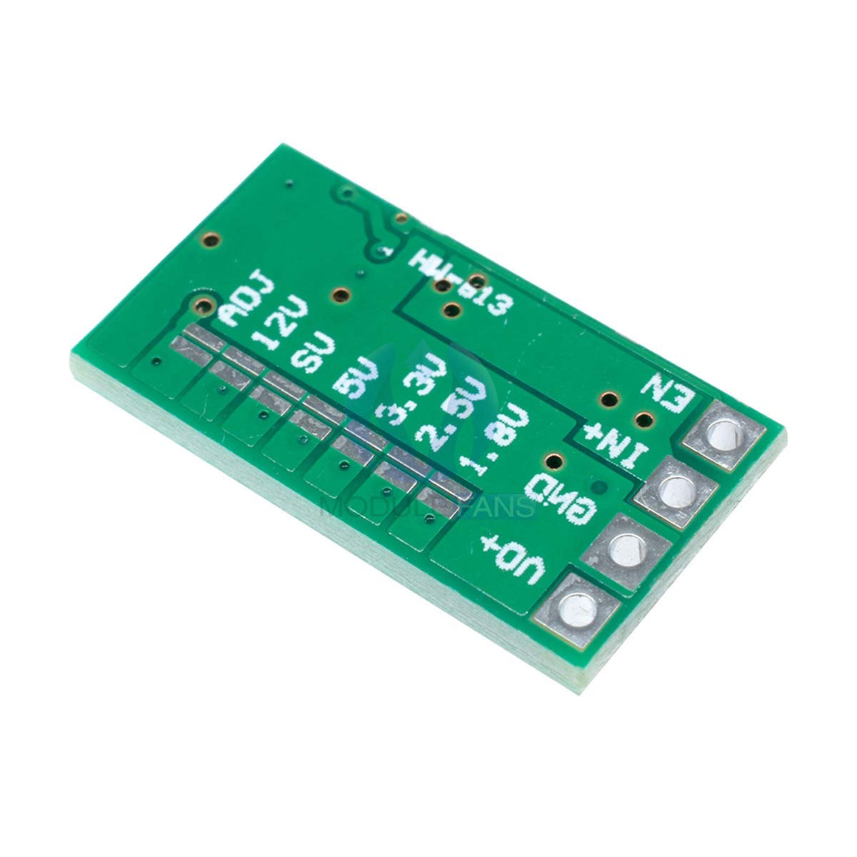
Figura 3: Abajo view of the module with fixed voltage selection pads.
3.2 volumen de salidatage Selección
The module offers two methods for setting the output voltage: adjustable via a potentiometer or fixed via solder pads on the back of the board.
Volumen de salida ajustabletage (0.8V - 17V)
- By default, the module is configured for adjustable output.
- Connect your input voltage to IN+ and GND.
- Use a small precision screwdriver (approx. 2mm blade width) to carefully turn the multi-turn potentiometer (located on the top side, see Figure 2) to achieve the desired output voltage.
- Supervisar el volumen de salidatage with a multimeter connected to VO+ and GND.
Volumen de salida fijotage (1.8V, 2.5V, 3.3V, 5V, 9V, 12V)
To use a fixed output voltage, modifications to the PCB are required. This process disables the adjustable potentiometer and activates one of the pre-set voltagy salidas.
- Identify the 'ADJ' pad and the fixed voltage pads (1.8V, 2.5V, 3.3V, 5V, 9V, 12V) on the bottom of the module (Figure 3).
- The adjustable potentiometer is active by default. To disable it and enable a fixed voltage, you must carefully cut the PCB trace connecting the 'ADJ' pad to the potentiometer circuit. This trace is typically a very thin line around the 'ADJ' pad. Use a sharp scalpel or hobby knife for this.
- Once the 'ADJ' trace is cut, solder a bridge across the two pads of your desired fixed voltage (e.g., for 5V output, solder across the 5V pads).
- Verify the modification with a multimeter before connecting any load.
Caution: Modifying the PCB requires precision and can damage the module if not performed correctly. Proceed with care.
4. Instrucciones de funcionamiento
Once the module is correctly wired and the output voltage is set, apply the DC input voltage within the specified range (4.5V to 24V). The module will then provide the set output voltage at VO+ and GND.
- Asegúrese de que el volumen de entradatage is always higher than the desired output voltage for proper step-down operation.
- Do not exceed the maximum output current of 3A. Exceeding this limit can lead to overheating and damage.
- For continuous operation, connect the EN (Enable) pin to IN+. If you wish to control the module's on/off state, apply a high signal (e.g., 3.3V or 5V) to EN for ON, and a low signal (GND) for OFF.
5. Mantenimiento
The Youmile DC-DC converter module is designed for reliable operation with minimal maintenance. Keep the module clean and free from dust and moisture. Avoid exposing it to extreme temperatures outside its operating range.
- Regularly inspect solder joints for integrity.
- Ensure adequate ventilation if operating at higher currents or in enclosed spaces to prevent overheating.
6. Solución de problemas
- Sin volumen de salidatage:
- Verifique el volumen de entradatage presence and polarity.
- Verify EN pin connection (should be high or connected to IN+ for operation).
- Asegúrese de que el volumen de entradatage is within the 4.5V-24V range and is higher than the desired output voltage.
- Inspect solder connections for continuity.
- Volumen de salida incorrectotage:
- If using adjustable mode, carefully re-adjust the potentiometer.
- If using fixed mode, ensure the 'ADJ' trace is properly cut and the correct fixed voltage pads are bridged. Refer to Section 3.2.
- Check for any accidental short circuits on the output.
- Sobrecalentamiento del módulo:
- Reduce the load current; ensure it does not exceed 3A.
- Provide better ventilation or consider a heatsink if operating continuously at high loads.
- No Input Reverse Connection Protection: This module does NOT have input reverse polarity protection. Connecting the input with reversed polarity will damage the module. Always double-check polarity before applying power.
- Protección de cortocircuito de salida: The module includes output short circuit protection. However, prolonged short circuits are not recommended and can still cause damage.
7. Especificaciones

Figura 4: Tabla de parámetros del producto.
| Parámetro | Valor |
|---|---|
| Tipo de módulo | Isolation Step-Down (BUCK) Synchronous Rectifier |
| Vol de entradatage | CC 4.5 V - 24 V |
| Vol de salidatage | Adjustable 0.8V - 17V; Fixed (1.8V, 2.5V, 3.3V, 5V, 9V, 12V) |
| Corriente de salida | 3A (Max); Test: 12V input, 1.5A output |
| Eficiencia de conversión | Up to 97.5% (e.g., 6.5V to 5V @ 0.7A) |
| Frecuencia de conmutación | 500 kHz |
| Ondulación de salida | 20mV (12V to 5V @ 3A, 20M bandwidth) |
| Temperatura de funcionamiento | -40°C a 85°C |
| Sobrevoltaje de salidatage Protección | No |
| Corriente estática | 0.85 mA |
| Regulación de carga | ±1% |
| VolumentagReglamento electrónico | ±0.5% |
| Velocidad de respuesta dinámica | 5% 200uS |
| Protección contra cortocircuito de salida | Yes (avoid prolonged short circuits) |
| Protección de conexión inversa de entrada | No |
| Control Enable | Sí |
| Tipo de conexión | Soldadura |
| Welding Hole Spacing | 2.54 milímetros |
| Dimensiones (largo x ancho) | 20.1 mm x 11 mm |
| Número de modelo | TS-YM-314 |
| Código Postal | 741416923933 |

Figure 5: Module dimensions.
8. Garantía y soporte
Specific warranty information for this product is not provided in the available data. For any technical support, questions, or warranty inquiries, please contact the seller or manufacturer directly through your purchase platform.


