Introducción
This manual provides detailed instructions for the WitMotion 16 Channel PWM Servo Motor Driver Controller Board. This board is designed for precise control of up to 16 servo motors, commonly used in robotics, model aircraft, and various electromechanical projects. It offers flexible connectivity options including USB and TTL UART, and supports offline control for enhanced convenience. The board features a high-performance STM32 series chip, ensuring stable operation and precise PWM accuracy.
Características del producto
- 16-Way Servo Control: Manages up to 16 individual servo motors simultaneously.
- Conectividad dual: Supports both USB and TTL UART connections for versatile integration.
- Velocidad ajustable: Allows for precise control over servo movement speed.
- Isolated Drive: Features an isolated drive design for stable performance and protection against board damage.
- Fuente de alimentación USB: Can be powered via USB for programming, eliminating the need for external drivers.
- State-Based Control: Simplifies programming by allowing users to define states rather than calculating detailed action parameters.
- Fuente de alimentación dual: Provides separate power inputs for the control board and servo motors (5-7.2V for servos), compatible with Arduino, Raspberry Pi, and other robotic systems.
Presupuesto
| Canales | 16 |
| Dimensiones | 43.5mm X 36mm X 12mm (Board), 7.87 x 3.94 x 1.97 inches (Product) |
| Posición del orificio de montaje | 37mm X 30mm, Aperture 3mm |
| Volumentage | USB: 5V, TTL: 3.3V (select one); Servo Motor Supply: 5-7.2V |
| Interfaz de comunicación | USB / TTL UART (Bluetooth optional) |
| Tasa de Baud | 9600Kps |
| Frecuencia | 48 MHz |
| PWM Accuracy | 0.1us |
| Number of Action Groups | 16 |
| Minimum Servo Step | 1us |
| Chip | STM32 series (high performance, low power consumption) |
| Temperatura de funcionamiento | -40℃ ~ 80℃ |
| Maximum Storage Actions | 8192 |
| Peso del artículo | 0.64 onzas |
Configuración
1. Power Supply and Basic Connections
Ensure the board receives appropriate power. The board itself can be powered via USB (5V) or TTL (3.3V). Servo motors require a separate power supply of 5-7.2V connected to the dedicated servo power input terminals.
2. Connecting to a Computer via USB
Connect the controller board to your computer using a standard USB cable. This connection is primarily used for programming and configuration. No additional drivers are typically required for basic functionality.

3. Connecting via TTL Serial Port
For communication with microcontrollers or other devices using TTL UART, connect the board's RX, TX, and GND pins to the corresponding pins on your device. Ensure voltage compatibility (3.3V for TTL).
4. Bluetooth Module Connection (Optional)
If using a Bluetooth module for wireless control, connect it directly to the designated Bluetooth interface on the board. Refer to the module's specific documentation for pairing and communication protocols.

5. Connecting to a Microcontroller
To integrate the servo driver board with a microcontroller (e.g., Arduino, Raspberry Pi, STM32), connect the microcontroller's VCC, TXD, RXD, and GND pins to the corresponding pins on the servo driver board. Ensure proper voltage levels and serial communication settings (baud rate 9600Kps).
Instrucciones de funcionamiento
1. State Control Method
The WitMotion servo driver board utilizes a state-based control method. Instead of calculating detailed servo movement parameters, you define specific 'states' for your servo motors. Each state can specify the position and speed for each of the 16 servos. The board then executes these predefined states sequentially or based on triggers.
2. Programming and Action Groups
The board supports up to 16 action groups and can store up to 8192 actions. This allows for complex sequences of movements to be programmed and stored directly on the board. You can define multiple states within each action group, specifying the duration (e.g., 1000ms) for each state.

3. ej.ample Application: Badminton Shuttle Machine
The 16-channel servo motor driver can be used in various applications, such as controlling a badminton shuttle machine. In such a setup, the board controls the steering gears to move components up, down, forward, and backward, precisely positioning and launching badminton shuttles. This can be automated or controlled remotely via a mobile phone if a Bluetooth module is integrated.
Video: 16-channel servo motor driver controls badminton serve. This video demonstrates a practical application of the WitMotion 16 Channel PWM Servo Motor Driver Board, showcasing its use in a badminton shuttle machine. It highlights the board's ability to control steering gears for precise movement and launching, with potential for remote control via mobile phone.
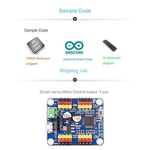
4.Sample Code and Libraries
WitMotion provides sample code and libraries to assist with programming, including examples for STM32 serial port programs, Arduino serial port libraries, and 51 serial port programs. These resources can be found on the official WitMotion website or support pages.

Mantenimiento
To ensure the longevity and optimal performance of your WitMotion 16 Channel PWM Servo Motor Driver Board, follow these maintenance guidelines:
- Manténlo limpio: Regularly clean the board with a soft, dry brush or compressed air to remove dust and debris. Avoid using liquids or harsh chemicals.
- Almacenamiento adecuado: Store the board in a dry, cool environment, away from direct sunlight, extreme temperatures, and high humidity. Use anti-static bags if available.
- Tratar con cuidado: Avoid physical shocks or excessive force on the board and its components. Always handle by the edges to prevent damage to sensitive parts.
- Inspeccionar las conexiones: Periodically check all wiring and connections for looseness or corrosion. Ensure power connections are secure and correctly polarized.
- Actualizaciones de firmware: Check the official WitMotion websitio para obtener actualizaciones de firmware disponibles que puedan mejorar el rendimiento o solucionar problemas conocidos.
Solución de problemas
If you encounter issues with your WitMotion 16 Channel PWM Servo Motor Driver Board, consider the following troubleshooting steps:
- Sin energía/Luces indicadoras apagadas:
- Verify that the power supply (USB or external) is correctly connected and providing the specified voltage (5V for USB, 3.3V for TTL, 5-7.2V for servos).
- Check the power cables for any damage or loose connections.
- Los servos no responden:
- Ensure the servo motors are correctly wired to the board and receiving adequate power from their dedicated supply.
- Confirm that the control signals (PWM) are being sent correctly from the board.
- Check your code or state definitions for correct servo addresses and target positions.
- Communication Issues (USB/TTL):
- Verify that the correct communication port is selected in your software.
- Ensure the baud rate (9600Kps) matches between the board and your communicating device.
- For TTL connections, double-check RX/TX wiring (RX to TX, TX to RX).
- If using PC software, ensure it is compatible with your operating system and properly installed. Some users have reported issues with software hanging; refer to WitMotion's official support for the latest software and drivers.
- Movimiento errático del servo:
- Check for electrical noise or interference. Ensure power supplies are stable.
- Review your code for incorrect timing or rapid changes in servo positions.
- Ensure the servo power supply can handle the current draw of all connected servos, especially under load.
For more detailed troubleshooting or specific technical issues, please refer to the official WitMotion support resources.
Información de garantía
Warranty terms for WitMotion products are typically provided at the point of purchase or can be found on the official WitMotion website. Please retain your proof of purchase for any warranty claims. The standard return policy allows for refunds or replacements within 30 days of purchase, subject to the seller's terms and conditions.
Apoyo
For further assistance, documentation, software, or video tutorials, please utilize the following resources:
- Oficial Websitio: Visita wiki.wit-motion.com/english for product documents, software, instructions, and apps.
- Unidad de Google: Access the WitMotion Google Drive for additional tutorials and resources.
- Canal de YouTube: Subscribe to the official WitMotion YouTube channel for instructional videos and project sharing.
- Contacto del fabricante: If direct support is needed, refer to the contact information provided on the WitMotion websitio.


