1. Información de seguridad
Lea y comprenda toda la información de seguridad y las instrucciones de funcionamiento antes de usar este multímetro. El incumplimiento de estas instrucciones podría provocar una descarga eléctrica, un incendio o daños al multímetro.
- Asegúrese siempre que los cables de prueba estén conectados correctamente y que el interruptor de función esté configurado en el rango correcto antes de realizar cualquier medición.
- No intente medir el vol.tages or currents exceeding the maximum rated values for this meter.
- Tenga mucho cuidado al trabajar con circuitos activos. Alto volumentagPuede ser peligroso.
- Never open the meter casing unless specifically instructed for battery or fuse replacement. Ensure test leads are disconnected before opening.
- Reemplace la batería cuando aparezca el indicador de batería baja para garantizar lecturas precisas.
- No utilice el medidor si parece dañado o si el aislamiento de los cables de prueba está comprometido.
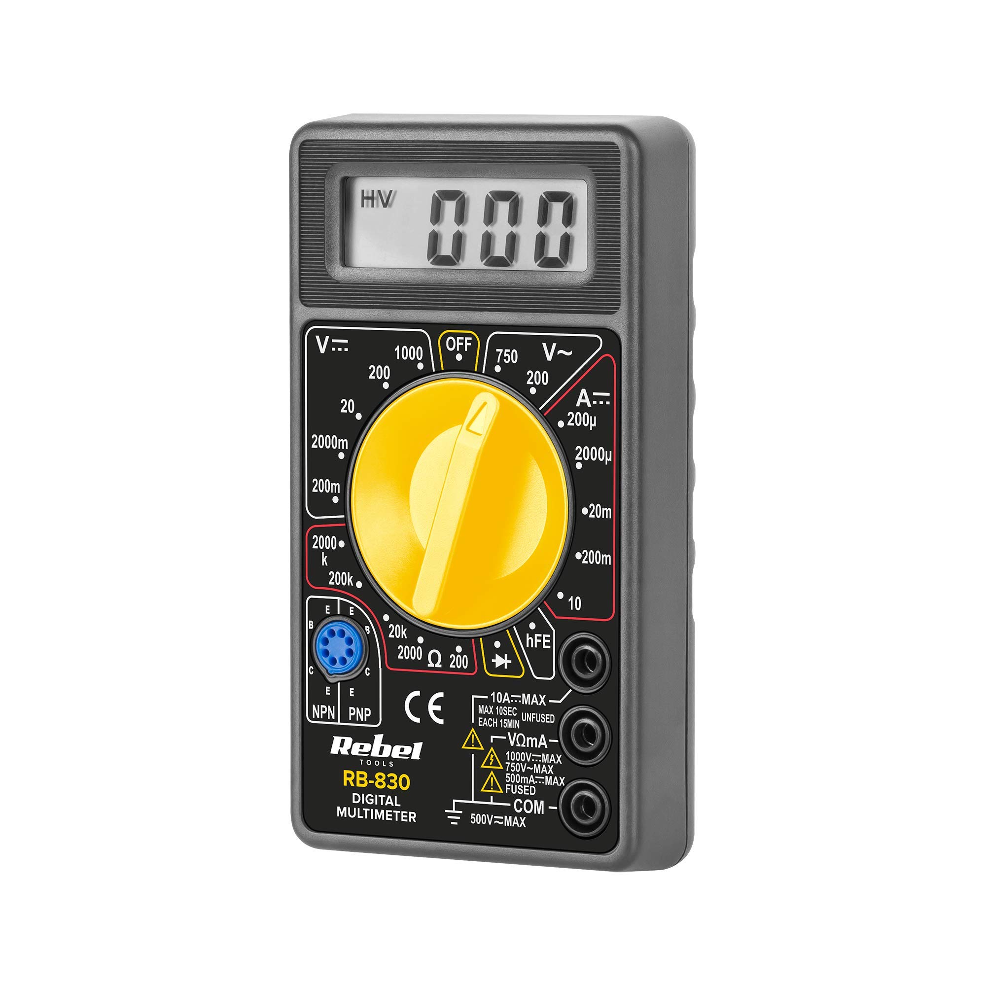
Figura 1: Trasero view of the Rebel MIE-RB-830 Multimeter, showing the battery compartment cover and a warning label. The label advises removing test leads before opening the case to avoid electrical shock and to install fuses with correct amp/volt ratings. It also indicates the power supply is a 9V battery, type NEDA 1604 9V 6F22.
2. Producto terminadoview
The Rebel MIE-RB-830 is a compact, battery-operated digital multimeter designed for measuring DC/AC voltage, DC current, resistance, diode, and transistor (hFE) values. It is suitable for general electrical testing and troubleshooting.
2.1. Componentes
- Digital Multimeter Unit
- Cables de prueba (rojo y negro)
- Batería de 9 V (puede estar incluida o venderse por separado)
- Manual de usuario (este documento)

Figura 2: The Rebel MIE-RB-830 Digital Multimeter shown with its accompanying red and black test leads. The multimeter features a large LCD display and a rotary function switch.

Figura 3: De cerca view of the red and black test leads. These leads are essential for connecting the multimeter to the circuit under test.
3. Configuración
3.1. Instalación de la batería
- Asegúrese de que el multímetro esté apagado y todos los cables de prueba estén desconectados.
- Localice la tapa del compartimiento de la batería en la parte posterior del medidor (consulte la Figura 1).
- Desatornille el/los tornillo(s) de retención y retire con cuidado la cubierta.
- Insert a new 9V battery (NEDA 1604 or 6F22 type), observing the correct polarity (+ and -).
- Vuelva a colocar la tapa del compartimiento de la batería y fíjela con el/los tornillo(s).
3.2. Conexión de los cables de prueba
- Conectar el rojo test lead to the "VΩmA" input jack.
- Conectar el negro test lead to the "COM" (common) input jack.
- For current measurements exceeding 200mA (up to 10A), connect the red test lead to the "10A" input jack.
4. Instrucciones de funcionamiento
4.1. Selección de funciones
Turn the rotary switch to the desired measurement function and range. Always start with a higher range if the approximate value is unknown to prevent overloading the meter.
4.2. Medición del volumen de CCtagy (V–)
- Coloque el interruptor giratorio en el volumen de CC deseado.tage (V–) range (e.g., 20V, 200V).
- Conecte el cable de prueba rojo al lado positivo (+) del circuito y el cable de prueba negro al lado negativo (-).
- Leer el vol.tage valor en la pantalla LCD.
4.3. Medición del volumen de CAtagy (V∼)
- Coloque el interruptor giratorio en el volumen de CA deseado.tage (V∼) range (e.g., 200V, 750V).
- Conecte los cables de prueba a través del voltaje de CA.tagy fuente.
- Leer el vol.tage valor en la pantalla LCD.
4.4. Medición de corriente continua (A–)
Precaución: To measure current, the meter must be connected in series with the circuit. Never connect the meter in parallel with a voltage fuente cuando esté en modo de corriente, ya que esto puede dañar el medidor y el circuito.
- Set the rotary switch to the desired DC Current (A–) range (e.g., 20mA, 200mA, 10A).
- For currents up to 200mA, ensure the red lead is in the "VΩmA" jack. For currents up to 10A, move the red lead to the "10A" jack.
- Abra el circuito donde se va a medir la corriente y conecte el medidor en serie.
- Lea el valor actual en la pantalla LCD.
4.5. Medición de la resistencia (Ω)
Precaución: Asegúrese de que el circuito o componente bajo prueba esté desenergizado antes de medir la resistencia.
- Set the rotary switch to the desired Resistance (Ω) range (e.g., 200Ω, 2kΩ, 200kΩ).
- Conecte los cables de prueba al componente o circuito que se va a medir.
- Lea el valor de resistencia en la pantalla LCD.
4.6. Prueba de diodo (→|–)
- Set the rotary switch to the Diode Test (→|–) position.
- Conecte el cable de prueba rojo al ánodo del diodo y el cable de prueba negro al cátodo.
- La pantalla mostrará el volumen hacia adelante.tagcaída de tensión (normalmente entre 0.5 V y 0.8 V para diodos de silicio).
- Invierta los cables. La pantalla debería mostrar "OL" (bucle abierto) para un diodo en buen estado.
4.7. Prueba de transistores (hFE)
- Coloque el interruptor giratorio en la posición hFE.
- Identifique si el transistor es NPN o PNP.
- Insert the transistor's emitter, base, and collector leads into the corresponding sockets on the hFE test socket.
- Lea el valor hFE (ganancia de corriente CC) en la pantalla.
5. Mantenimiento
5.1. Reemplazo de la batería
Cuando aparezca el indicador de batería baja en la pantalla, reemplace la batería de 9 V como se describe en la Sección 3.1. Usar una batería baja puede generar lecturas inexactas.
5.2. Reemplazo de fusibles
If the current measurement function stops working, the fuse may need replacement. This operation should only be performed by qualified personnel.
- Asegúrese de que el multímetro esté apagado y todos los cables de prueba estén desconectados.
- Abre la parte trasera casing of the meter (this may involve more screws than just the battery compartment).
- Locate the blown fuse and replace it with a fuse of the exact same type and rating (e.g., F200mA/250V for mA range, F10A/250V for 10A range). Refer to the internal markings or specifications for precise fuse ratings.
- Carefully reassemble the meter, ensuring all screws are tightened.
5.3. Limpieza
Limpie el medidor con publicidadamp Paño y detergente suave. No utilice abrasivos ni disolventes. Mantenga el medidor seco.
6. Solución de problemas
| Problema | Posible causa | Solución |
|---|---|---|
| No hay pantalla o la pantalla es tenue | Batería baja o muerta | Reemplace la batería de 9V. |
| Lecturas incorrectas | Low battery; Incorrect range selection; Poor test lead connection | Replace battery; Select appropriate range; Ensure leads are firmly connected. |
| La medición actual no funciona | Blown fuse; Incorrect lead connection for current | Replace fuse (see Section 5.2); Ensure red lead is in "VΩmA" or "10A" jack as appropriate. |
| Se muestra "OL" (Sobrecarga) | Measured value exceeds selected range; Open circuit (for resistance/continuity) | Seleccione un rango más alto; Verifique que el circuito no tenga roturas. |
7. Especificaciones
| Función de medición | Rango | Exactitud |
|---|---|---|
| Vol DCtagy (V–) | 200mV, 2V, 20V, 200V, 1000V | ±(0.5% + 2 dígitos) |
| Vol. CAtagy (V∼) | 200 V, 750 V | ±(1.2% + 10 dígitos) |
| DC Current (A–) | 200 µA, 2 mA, 20 mA, 200 mA, 10 A | ±(1.0% + 2 dígitos) |
| Resistencia (Ω) | 200Ω, 2kΩ, 20kΩ, 200kΩ, 2MΩ | ±(0.8% + 2 dígitos) |
| Prueba de diodo | Sí | Vol hacia adelantetage gota |
| Prueba de transistores (hFE) | Sí | hFE value |
| Fuente de alimentación | 9V Battery (NEDA 1604 or 6F22) | |
| Mostrar | 3½ Digit LCD, Max. 1999 | |
| Dimensiones | Aprox. 13.5 x 10 x 4 cm | |
| Peso | Approx. 107 grams (without battery) | |
| Temperatura de funcionamiento | 0 °C a 40 °C (32 °F a 104 °F) | |
| Temperatura de almacenamiento | -10 °C a 50 °C (14 °F a 122 °F) | |
| Normas de seguridad | CE, RoHS |
8. Garantía y soporte
This Rebel MIE-RB-830 Digital Multimeter is covered by a standard manufacturer's warranty against defects in materials and workmanship. Please refer to the warranty card included with your purchase or contact your retailer for specific warranty terms and conditions.
For technical support or service inquiries, please contact the point of purchase or visit the official Rebel websitio para información de contacto.


