1. Introducción
This manual provides essential information for the safe and efficient installation, operation, and maintenance of the DANFOSS BFP 21R3 Burner Oil Pump, model number 071N0109. Please read this manual thoroughly before attempting any installation or operation to ensure proper function and to prevent damage or injury. Keep this manual for future reference.

Figura 1: General view of the DANFOSS BFP 21R3 Burner Oil Pump.
2. Información de seguridad
Always observe general safety precautions when working with fuel systems and electrical components. Failure to follow these instructions may result in property damage, serious injury, or death.
- Ensure the power supply to the burner system is disconnected before installation, maintenance, or troubleshooting.
- Use equipo de protección personal (EPP) adecuado, incluidos guantes y protección para los ojos.
- Handle fuel with care. Fuel is flammable and can cause skin irritation.
- La instalación y el servicio sólo deben ser realizados por personal calificado.
- Compruebe si hay fugas después de la instalación y antes de operar el sistema.
- Do not modify the pump or its components. Use only genuine DANFOSS replacement parts.
3. Producto terminadoview
The DANFOSS BFP 21R3 is a compact burner oil pump designed for use in oil burner systems. It is engineered for reliable fuel delivery and pressure regulation. The pump features a robust metal construction and is suitable for industrial applications.

Figura 2: Lado view of the pump, highlighting the 'P' (pressure) and 'V' (return) ports, and model identification.
Las características principales incluyen:
- Modelo: BFP 21R3
- Número de pieza: 071N0109
- Material: Metal
- Color: Negro
- Solicitud: Burner Oil Systems

Figura 3: Arriba view of the pump, showing the electrical connector for power supply.
4. Configuración e instalación
Proper installation is crucial for the pump's performance and longevity. Refer to your burner manufacturer's instructions for specific mounting requirements.
4.1 Montaje
- Mount the pump securely to the burner motor or a stable surface using appropriate fasteners.
- Ensure the pump shaft aligns correctly with the motor coupling.
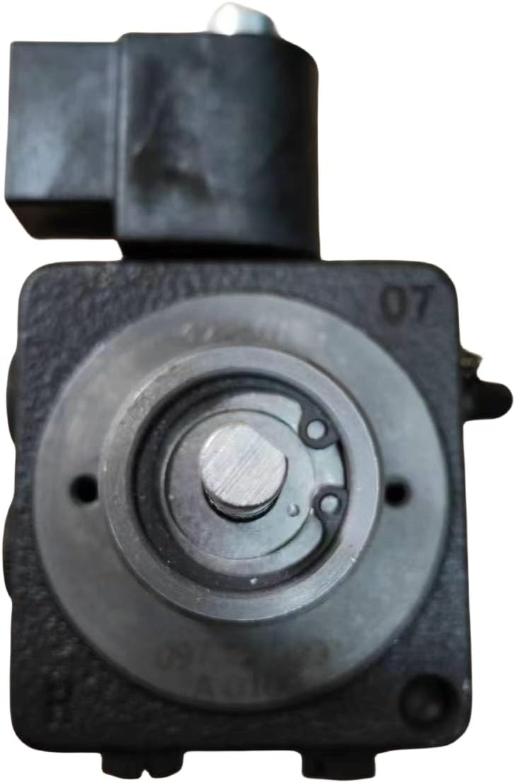
Figura 4: Abajo view of the pump, illustrating the drive shaft and mounting screw locations.
4.2 Conexiones de la línea de combustible
Connect the fuel lines as follows:
- Inlet (Suction) Line: Connect the fuel supply line to the designated inlet port. Ensure a tight, leak-free connection.
- Nozzle Line (Pressure): Connect the line leading to the burner nozzle to the pressure port (marked 'P' on some models).
- Línea de retorno: If applicable, connect the return line to the return port (marked 'V' on some models) to send excess fuel back to the tank. For single-pipe systems, the return port must be plugged.
4.3 Conexiones eléctricas
Connect the pump's electrical terminals to the burner control system according to the burner manufacturer's wiring diagram. Ensure correct voltage and polarity. All electrical work must comply with local codes and regulations.
4.4 Cebado de la bomba
After installation, the pump must be primed to remove air from the fuel lines. This is typically done by running the burner for a short period until a steady flame is established. Some pumps may have a bleed screw for manual air removal.
5. Instrucciones de funcionamiento
Once installed and primed, the DANFOSS BFP 21R3 pump operates automatically in conjunction with the burner control system. The pump maintains the required fuel pressure for efficient combustion.
5.1 Ajuste de presión
The pump's pressure can be adjusted via a pressure regulating screw, typically located on the pump body. Use a pressure gauge to set the desired operating pressure as specified by the burner manufacturer. Turn the screw clockwise to increase pressure and counter-clockwise to decrease pressure.
6. Mantenimiento
Regular maintenance ensures optimal performance and extends the life of the pump.
6.1 Controles de rutina
- Inspect fuel lines for leaks, cracks, or damage.
- Compruebe las conexiones eléctricas para comprobar su estanqueidad y ausencia de corrosión.
- Escuche ruidos inusuales durante el funcionamiento, que pueden indicar un problema.
6.2 Reemplazo del filtro
The pump typically contains an internal filter that should be inspected and replaced periodically, usually annually or as recommended by the burner manufacturer. A clogged filter can restrict fuel flow and reduce pump performance.

Figure 5: Close-up of the pump's drive shaft, which connects to the motor.
7. Solución de problemas
This section outlines common issues and potential solutions. Always disconnect power before performing any troubleshooting steps.
| Problema | Posible causa | Solución |
|---|---|---|
| Sin flujo de aceite | Clogged filter, air in lines, faulty motor, incorrect rotation | Clean/replace filter, bleed air, check motor, verify pump rotation |
| Baja presión de aceite | Clogged filter, worn pump components, incorrect pressure setting | Clean/replace filter, inspect pump, adjust pressure regulator |
| Ruido excesivo | Air in lines, loose mounting, worn bearings | Bleed air, tighten mounting bolts, inspect for wear |
| Fugas de aceite | Loose fittings, damaged seals | Tighten connections, replace seals |
8. Especificaciones
| Especificación | Valor |
|---|---|
| Fabricante | DANFOSS |
| Número de modelo | BFP 21R3 |
| Número de pieza | 071N0109 |
| Material | Metal |
| Color | Negro |
| Estilo | Industrial |
9. Garantía y soporte
For warranty information or technical support, please contact your authorized DANFOSS dealer or the seller from whom the product was purchased. Keep your proof of purchase for warranty claims.